2-10 Dell PowerVault 720N, 740N, and 760N Installation and Troubleshooting Guide
)''%
A cable management kit is provided with the filer. This kit consists of a large plastic
cable management clip and two self-tapping screws. When properly installed, cables
are routed from the back of the filer, through the circular loop of the plastic cable man-
agement clip, to the PowerVault 700N storage system, network receptacle, or to the
tape backup device.
Cables routed through the cable management clip represent a service loop at the
back of the filer. When a trained service technician needs to perform service inside
the filer, the cable management clip is opened and the cables are released from the
clip. The technician opens the drawer on the back of the filer without putting unneces-
sary tension on installed cable connections.
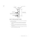
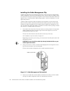
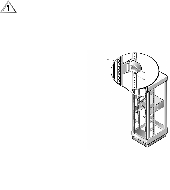
1. At the back and to the side of the rack, locate a mounting location for the plastic
cable management clip on the left or right vertical rack supports, two to four
inches above the back of the filer.
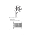
The clip must be oriented so that the latch is at the top of the clip.
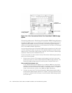
Your installation may look similar to Figure 2-7.
Depending on the rack you are using, you may have to first drill a pilot hole for the
self-tapping screws.
(%%
2. Using a nut driver or wrench, install the self-tapping screws through the mount-
ing holes at the location you have selected.
Ensure that the cable management clip is easily opened and closed.
.:-(%
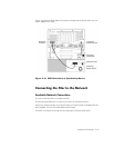
3. Later, as you install and connect cables to the back of the filer, route the cables
through the cable management clip to the appropriate connector.
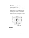
select any two holes


