


34
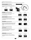
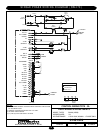
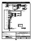
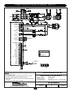
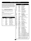
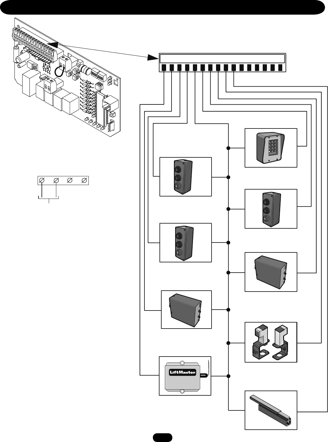
CONTROL CONNECTION DIAGRAMS
12345678910111213141516
R2
R1
R4
R3
3
6
9
#
2
5
8
0
1
7
OPEN
CLOSE
STOP
OPEN
CLOSE
STOP
OPEN
CLOSE
STOP
FREQ
FREQ
NOTE: See wiring diagrams shipped with kit for
additional information. See owner’s manual for wiring
distances and wire gauge information.
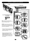
WARNING: All controls that are to be used to operate
the gate system, MUST be installed where the user
cannot come into contact with the gate while operating
the controls. Also, always install the controls where the
user has full view of gate operation.
* All inputs are normally open and momentary, except
the stop (N.C.). The following instructions are based
upon UL325, and include recommendations for
significant increase in safety.
* We strongly recommend that you follow the UL
guidelines presented throughout the manual.
Installation device instructions – always follow the
instructions provided by the manufacturer when
installing and adjusting any control device. If these
instructions are contrary to the advice given here,
call for assistance.
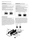
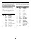
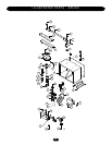
24 Vac ACCESSORY POWER MAY BE FOUND ON
THESE TERMINALS
24 Vac
HARD CLOSE CONTROL
INPUT (N.O.)
STOP/RESET
CONTROL INPUT (N.C.)
SHADOW LOOP
INPUT (N.O.)
RESIDENTIAL RADIO
(SINGLE BUTTON) INPUT (N.O.)
SOFT OPEN
INPUT (N.O.)
HARD OPEN
CONTROL INPUT (N.O.)
INTERRUPT (SAFETY) LOOP
INPUT (N.O.)
OBSTRUCTION OPEN
EDGE/PHOTO EYE INPUT (N.O.)
OBSTRUCTION CLOSE
EDGE/PHOTO EYE INPUT (N.O.)
J1 TERMINAL BLOCK
GL BOARD