


1616
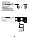
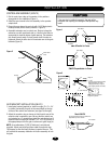
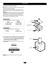
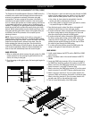
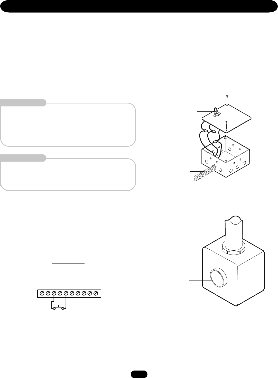
ON/OFF SWITCH POWER WIRING
NOTE: Before running power wiring refer to wiring specifications
on page 15 for correct wire gauges.
Secure all electrical power connections inside the disconnect
switch electrical box. Refer to electrical wiring diagrams on pages
31-33.
IMPORTANT: On three phase operators, power connections must
be properly phased. If phased incorrectly, the gate operator will
run reversed. To correct this situation, shut off power at main
power source and at the operator’s electrical disconnect switch.
Then reverse any two of the three power leads.
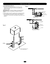
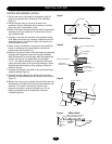
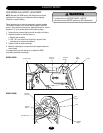
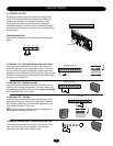
STOP/RESET BUTTON CONTROL WIRING (REQUIRED)
1. This control will function as a Stop/Reset command and is to
be wired within line of sight of the gate. The operator will not
function unless this circuit is completed.
2. Wire control station to terminals 3 and 5 in the control box on
the operator.
J1 CONNECTOR
STOP/RESET
Button
Control Conduit
STOP/RESET BUTTON WIRING
STOP/RESET
1 2 3 4 5 6 7 8 9 10
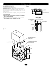
WIRING
SINGLE PHASE
All single phase operators will have the following:
115V 208/230V
• L1 (NEUTRAL), WHITE • L1 (HOT), BLACK
• L2 (HOT), BLACK • L2 (HOT), BLACK
• GROUND, GREEN • GROUND, GREEN
Wire Nut Connections
(See Instructions)
ON/OFF Switch
Cover
Power Wiring Conduit
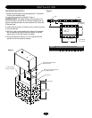
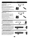
THREE PHASE
All three phase operators will have the following:
• L1 BLACK • L2 BLACK
• L3 BLACK • GROUND, GREEN
NOTE: For additional control station options refer to pages
21 and 22.