


12
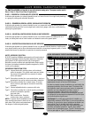
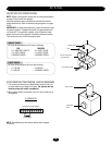
CONTROL ARM ASSEMBLY (SW470)
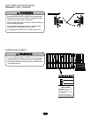
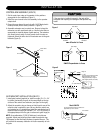
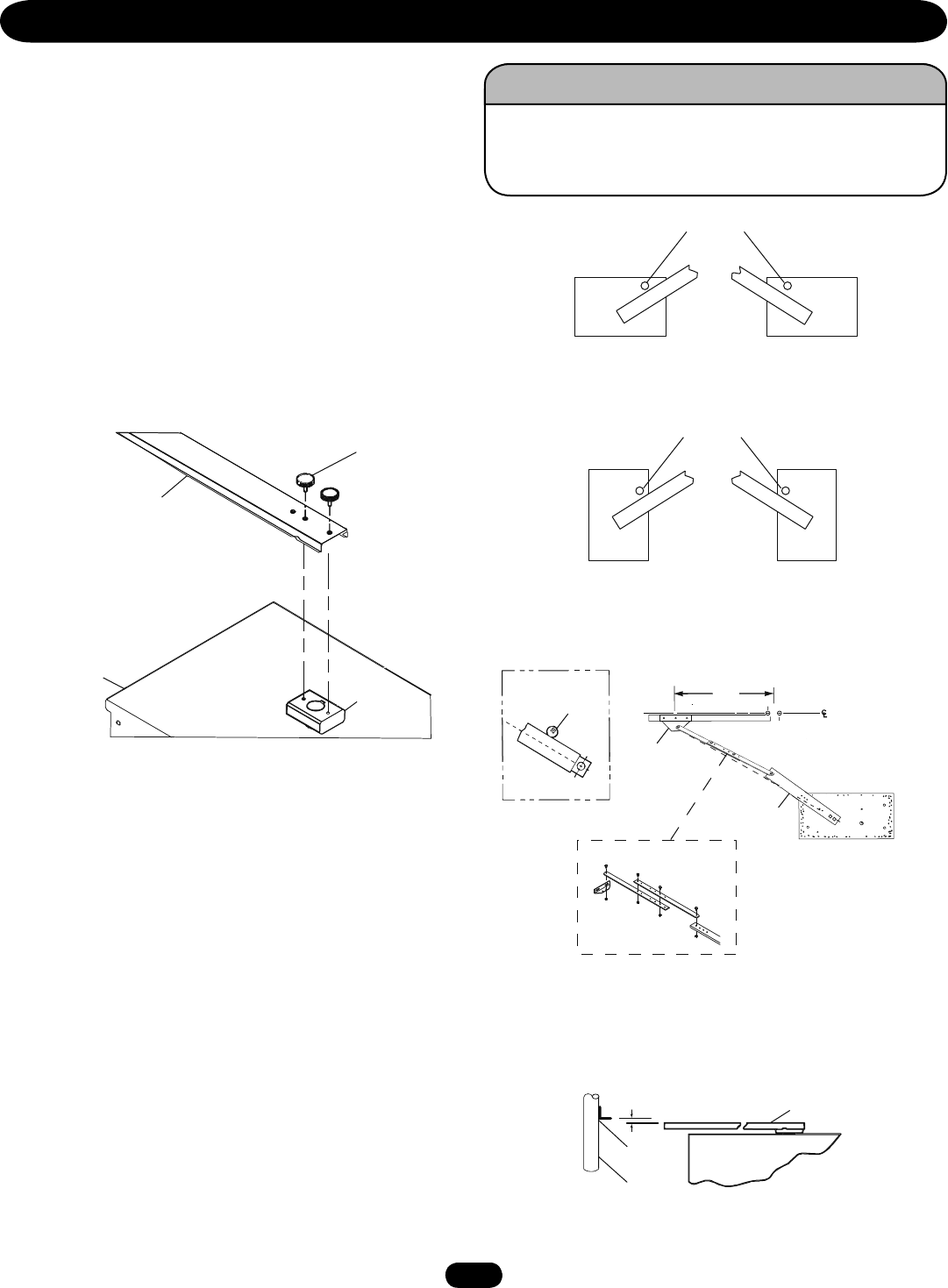
1. Set the control arm stop on the operator in the positions
appropriate for the installation (Figure 1).
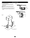
2. Install the arm channel to the hub assembly to the operator
output shaft.
3. Secure the arm channel to arm hub with 1/4-20 black plastic
knobs provided (Hub is factory installed - Figure 2).
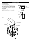
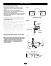
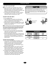
4. Assemble extension arm to control arm. Be sure to keep the
extension arm with spot-faced side up. Use the holes that are
appropriate for desired degree of gate opening. The extension
arm should swivel easily on pivot screws when the nuts are
tightened. Attach the other end of the actuator arm to the gate
brackets (Figure 3).
12
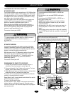
INSTALLATION
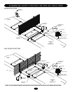
If the arm stop is installed incorrectly, the gate will be
prevented from opening and damage to the operator may
result!
ATTENTION
AVERTISSEMENT AVERTISSEMENT
AVERTISSEMENT
WARNING
CAUTION CAUTION
WARNING
WARNING
PRECAUCIÓN
ADVERTENCIA
ADVERTENCIA ADVERTENCIA
Figure 1
Close Stops
SW470 Parallel to Fence
Left hand
installation
Right hand
installation
Close Stops
“L.H.”
“R.H.”
SW470 Perpendicular to Fence
Figure 2
Arm Channel
Housing
Hub
Assembly
Black Plastic
Knob
Figure 3
Gate
Plate
Crank Extension
NOTE: Dotted line indicates
straight arm position
Eccentric stop (operating position
after adjustment). Arm must
swing approximately 2 degrees
past straight position (See detail)
36"
Hinge Pin
Extension arm
installation detail
Installation Detail
Eccentric stop during
installation of gate
plate
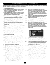
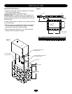
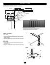
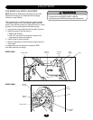
GATE BRACKET INSTALLATION (SW470)
1. Install gate bracket (supplied) or install an angle (2" x 2" x 1/4"
by others) horizontally on gate, at the same height as the top
surface of the control arm extension (see figure to the right).
2. Adjust the eccentric stop as shown so that the wide area of the
eccentric stop is against the arm. Be sure that the control arm
and actuator are in a straight line. Install the gate bracket and if
required install an angle (for SW490 2" x 2" x 1/4" by others) at
the appropriate point on the gate in reference to gate hinge pin.
NOTE: As an alternative, (2) 3/8-16 bolts and a nut plate are
provided. Adjust arm length and then rotate the eccentric stop
180 degrees so that the small thickness is against the arm. This
will provide the necessary deflection in the arm assembly to lock
the gate.
Model SW470
Gate
Bracket
Gate
Top of gate bracket should be mounted 1/2"
higher than top of arm channel
Arm Channel