


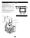
11
11
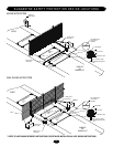
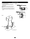
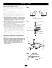
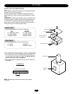
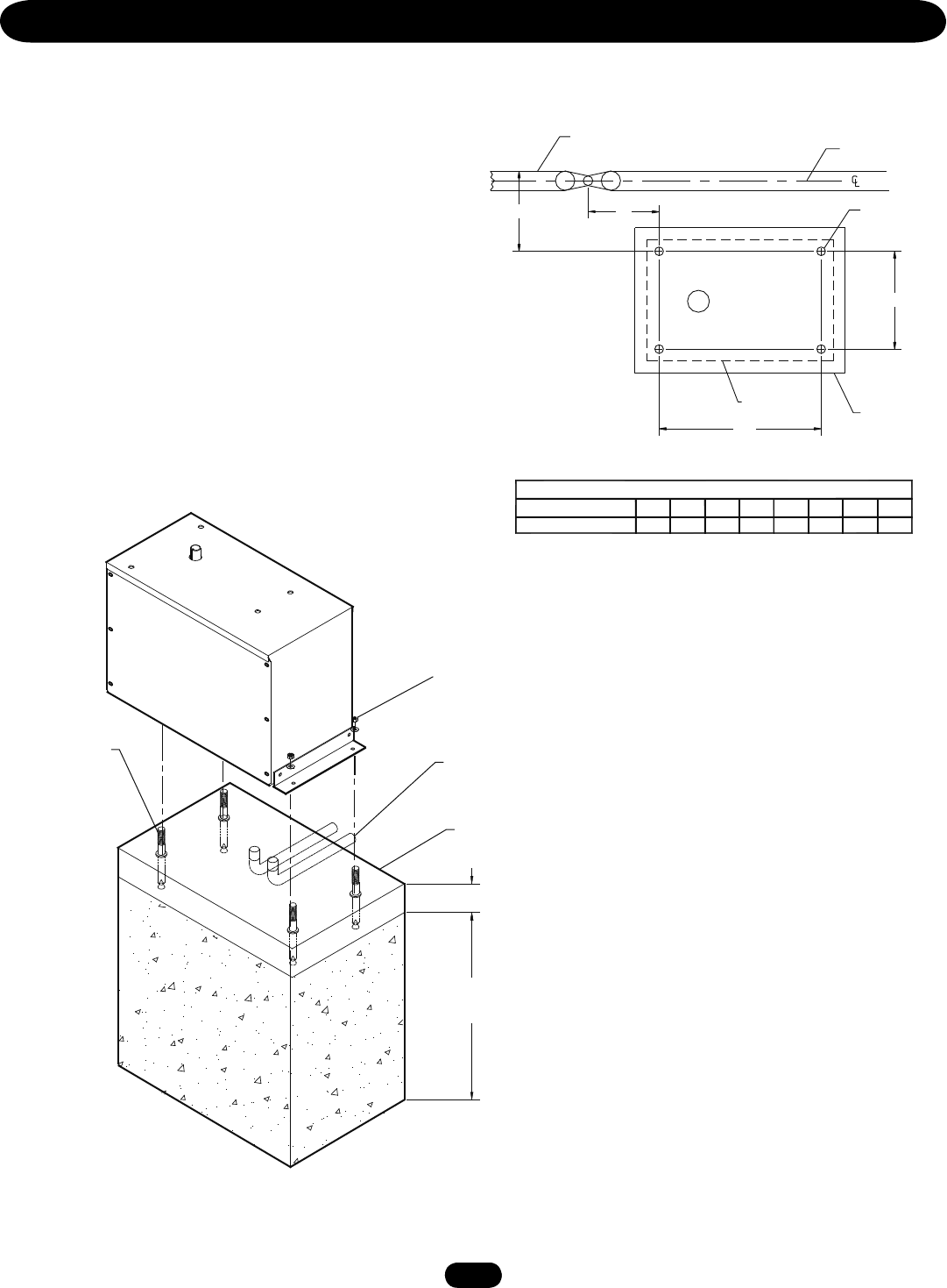
PAD MOUNTING (SW490)
1. Measure the gate length and select appropriate “P” dimension
from the gate installation table.
2. Layout the concrete pad as detailed in Figure 1.
IMPORTANT NOTE: The relative location of the operator to the
fence and the gate is critical. Be sure that the measurements for
operator mounting are taken from the centerline of the fence and
of the gate hinge.
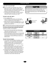
3. Locate electrical conduit, as required, prior to pouring concrete.
4. Pour concrete pad.
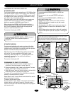
5. Bolt the (2) pad mount brackets to the bottom of the operator
with the hardware provided (Install the operator so that the
output shaft is on the side closest to the gate).
6. Secure the operator to the pad. It is very important that the
operator be level and square to the gate.
Figure 1
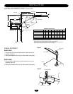
Figure 2
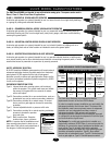
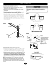
INSTALLATION
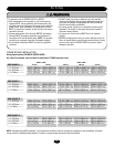
SW490 GATE OPERATOR INSTALLATION TABLE
GATE LENGTH (FEET)
P DIMENSION IN INCHES
8-9 10-11 12-13 14-15 16-17 18-19 20-21 22
21.9 25.3 28.8 32.3 35.7 39.2 42.7 46.1
Operator
8"
1/2" Redhead
(4 Required)
5"
Output
Shaft
28"
Concrete Pad
18" x 34" min.
Fence
Gate
P
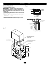
Using suitable hardware secure
operator to L-bolts
Power and control wiring should be
run in separate conduit
Concrete Pad
Depth required by
local codes or below
frost line
2" to 4" above grade
1/2" red head bolts or
anchors (4 required)