


1414
INSTALLATION
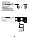
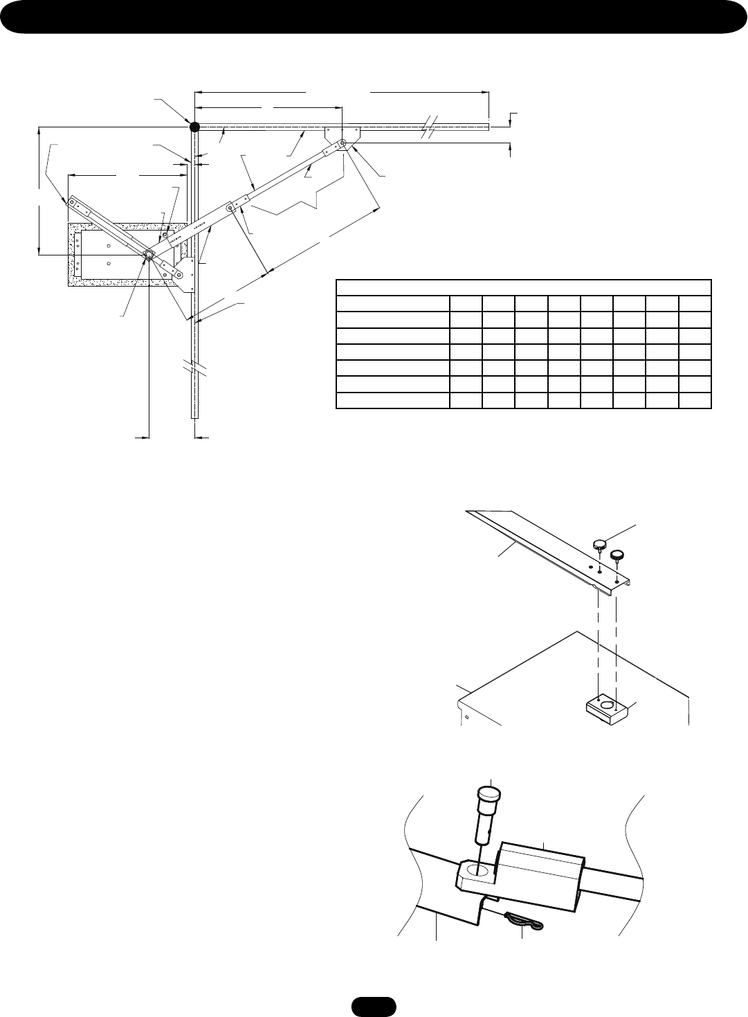
CONTROL ARM ASSEMBLY (SW490) continued
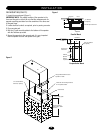
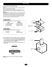
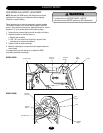
MANUAL DISCONNECT
MODEL SW470
1. Remove the (2) black knobs securing the control arm to the
operator (Figure 1).
2. Swing arm assembly off to the side. Gate should swing freely.
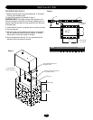
MODEL SW490
1. Remove hitch pin and pivot pin securing control arm to arm
assembly (Figure 2).
2. Swing arm assembly off to the side. Gate should swing freely.
Figure 1
Arm Channel
Housing
Hub
Assembly
Black Plastic
Knob
Extension Arm Holder
Extension Arm
Cotter Pin
Pivot Pin Assembly
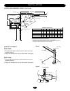
Figure 2
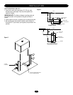
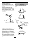
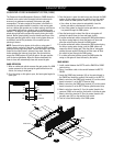
Gate Hinge
Gate Length
A
4.5"
Open gate position
B
Gate Bracket
Gate Center Line
Output Shaft
Control arm hub
assembly
Control arm
extension
Y
D
Extension
Arm
Extension
Arm Holder
Closed
gate
position
90º
34"
2"
Pipe
C
13"
X
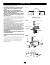
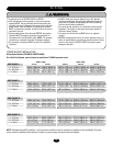
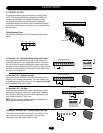
Gate Length (Feet) 8-9 10-11 12-13 14-15 16-17 18-19 20-21 22
A Dimension (Inches) 4.5 4.5 4.5 4.5 4.5 4.5 4.5 4.5
B Dimension (Inches) 24 30 36 42 48 54 60 66
C Dimension (Inches) 13 13 13 13 13 13 13 13
D Dimension (Inches) 25.9 29.3 32.8 36.3 39.7 43.2 46.7 50.1
X Dimension (Inches) *25.7 *29 *32.8 *36.9 *41.2 *45.6 *50 *54.6
Y Dimension (Inches) **17 **20.6 **23.8 26.6 29.3 31.8 34.2 36.6
All table dimensions are measured from pivot to pivot.
* Cut/add excess pipe for desired extension arm pivot to pivot dimension.
** Cut excess control arm extension and/or control arm hub assembly for desired pivot to
pivot dimension. Weld or bolt extension arm to arm assembly.
Closed gate stop
SW490 Gate Installation Table