


27
Troubleshooting
GATE WILL NOT OPEN OR CLOSE
Test the operator to find out whether the open input devices are functioning by following these steps.
nn
nn
n If a remote
control is being used to open the gate, try another remote control or try using a push button if there is one installed.
oo
oo
o If a
push button is being used try using another push button or a remote control.
pp
pp
p If there is no push button installed the gate
may be operated by connecting a jumper wire to terminal 8 and momentarily touching it to terminal 5 or 7.
qq
qq
q If the remote
controls are not working, see TRANSMITTER DOES NOT WORK on the previous page.
rr
rr
r Check the manual release switch
to make sure it is in the operate (up) position.
ss
ss
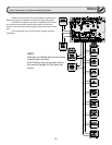
s Check to see which LEDs are illuminated on the circuit board. For normal
operating conditions the only LEDs that should be illuminated are the stop input at terminal 9 and Limit Switch 1 input if the
gate is in the fully open position or Limit Switch 2 input if the gate is in the fully closed position.
tt
tt
t If any of the input LEDs
are illuminated on terminals 4, 5, 7 or 10, disconnect wires from that input terminal that is illuminated until the LED is
extinguished to determine which input device may be stuck.
uu
uu
u If the stop input LED on terminal 9 is not illuminated, check
the stop input device if any are installed and all connections to the device. If no stop input device is installed make sure that
there is a jumper between terminals 8 and 9 and that it is securely fastened. v Check the circuit breaker button. If the circuit
breaker is tripped, press it back in. w Make sure there is power to the circuit board on terminals 13 and 14.
THE GATE WILL NOT STOP OR REVERSE WHEN IT MEETS AN OBSTRUCTION
nn
nn
n Adjust the gate sensitivity. The operator needs to be adjusted for more sensitivity. This is done by turning the
open and close gate sensitivity adjustments clockwise for more sensitivity. (See page 17).
GATE WILL NOT STAY CLOSED
nn
nn
n Make sure that the Right/Left Side operation switch is in the correct position (See page 17). If the Right/Left Side
operation switch is in the incorrect position, the auto close timer feature may be working in reverse and telling the gate
operator to open after the auto close time has elapsed.
oo
oo
o Check to see if any input LEDs on terminals 4, 5 or 7 flicker or
illuminate when the gate gets to the closed position.
pp
pp
p If any of the input LEDs flicker or illuminate on terminals 4, 5, or 7,
disconnect wires from that input terminal that is illuminated until the LED is extinguished to determine which input device
may be activating.
TIMER WILL NOT CLOSE THE GATE
nn
nn
n Make sure that the Right/Left Side operation switch is in the correct position (See page 17). If the Right/Left Side
operation switch is in the incorrect position, the auto close timer feature may be working in reverse and telling the gate
operator to open instead of close after the auto close time has elapsed.
oo
oo
o Make sure the auto close timer switch is in the
ON position (See page 17). The auto close timer switch is located on the right edge of the circuit board.
pp
pp
p Adjust the
amount of auto close time (See page 17). The auto close time may be set too high and is simply taking a long time to close.
Do not continue pressing the remote control or other open or safety input devices because each time an open or a safety
input is given the timer will reset and begin counting over.
OPERATOR RUNS IN ONLY ONE DIRECTION
nn
nn
n Check to see which LEDs are illuminated on the circuit board. For normal operating conditions the only LEDs that
should be illuminated are the stop input at terminal 9 and Limit Switch 1 input if the gate is in the fully open position or Limit
Switch 2 input if the gate is in the fully closed position.
oo
oo
o If any of the input LEDs are illuminated on terminals 4, 5, 7 or 10,
disconnect wires from that input terminal that is illuminated until the LED is extinguished to determine which input device
may be stuck.