


15
GRY
GRY
1
2
3
4
BLK
RED
SAFETY
N.O.
N.O.
N.O.
N.C.
N.O.
N.O.
OPEN
PULSE OPEN
N.C.STOP
CLOSE
N.O.STOP
412 HM
RADIO RECEIVER
)
)
)
)
)
)
REMOVE JUMPER
IF USING N.C. STOP
PUSH BUTTONS,
KEY SWITCHES, ETC.
24
SWITCH1
RED
LEFT/RIGHT SIDE
OPERATION
L R
OFFON
SWITCH2
ORG
COM
GRN
1
2
3
4
SAFETY
OPEN
OPEN
ADJUST
OPEN
ADJUST
TIMER
ADJUST
TIMER
ADJUST
TIMERSWITCH
CLOSE
ADJUST
CLOSE
ADJUST
MOTORPOWER
RELAY
NOTUSED
NOTUSED
RELAYPOWER
RELAYCOIL
RELAYCOIL
START/STOP
RESITOR
START/STOP
RESITOR
A
CCESSORYINPUTTERMINALS
A
CCESSORYINPUTTERMINALS
LIMITSWIT
CHES
SWITCH
SENSITIVITY
ADJUSTMENTS
AUTO
CLOSE
TIMER
AUTO
CLOSE
TIMER
PULSE
OPEN
PULSE
OPEN
N.C.
STOP
N.C.
STOP
N.O.
STOP
N.O.
STOP
A
CCESSORYPOWER
12V
OLTDC/.1AMP
A
CCESSORYPOWER
12V
OLTDC/.1AMP
CIRCUIT
BOARD
POWER
CIRCUIT
BOARD
POWER
CLOSE
5
6
7
8
9
10
11
12
13
14
15
-
+
+
+
-
-
RESISTOR
RESISTOR
INCREASE
INCREASE
MORETIME
JUMPER18VAC
COM COM COM
EDGE ALARM RADIOCOM
BLU
BLU
VLT
VLT
ORG GRN BLKYLW
YLW
BLU
BLU
16
17
18
19
20
21
22
23
25 26 27
!
104680F
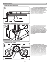
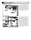
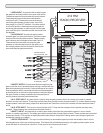
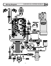
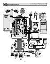
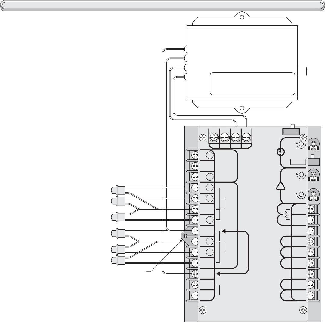
N.C. STOP INPUT: Any device that is used to stop the gate operator while it is running in the open or closed
direction is a stop input device. These stop input devices must provide normally closed contacts. To connect these normally
closed contacts, remove the stop jumper from terminals 8 and 9 and then connect the contacts to these same terminals 8
and 9.
N.O. STOP INPUT: This input functions identical to N.C. Stop with the exception that it requires normally open
contacts. These contacts are connected to terminals 9 and 11.
SAFETY INPUT: Any device that is used to open and/or hold open the gate while the gate is in a non-closed
position is a safety input device. The safety input device must provide normally open contacts. These contacts are connected
to terminals 4 and 6. This function is especially useful when the auto close timer is being used in preventing the gate from
accidentally closing on a vehicle.
PULSE OPEN INPUT: This input functions similarly to the standard open input with the exception that it will not
hold the gate open if the input remains present. This feature will add additional security to the gate operator system in the
event that there is a device that is stuck on. Pulse open is found at terminals 6 and 7.
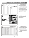
SAFETY NOTES: Controls must be far enough from the
gate so that the user is prevented from coming in contact with the
gate while operating the controls. Controls intended to be used to
reset an operator after 2 sequential activations of the entrapment
protection device or devices must be located in the line of sight of
the gate. Outdoor or easily accessible controls shall have a
security feature to prevent unauthorized use.
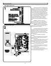
OPEN INPUT: Any device that is used to open
the gate from a closed position is an open input device.
The device used must provide normally open contacts.
These normally open contacts are connected to
terminals 5 and 6. These open input terminals will
cause the gate operator to open and/or close if the
timer switch is in the OFF position. If the timer switch
is in the ON position, these open input terminals will
cause the gate operator to open and will hold the gate
open until the input is released and the auto close time
has elapsed.
CLOSE INPUT: Any device that is used to
close the gate is a close input device. The device used
must provide normally open contacts. These normally
open contacts are connected to terminals 9 and 10.
These close input terminals will cause the gate
operator to close the gate any time the gate is in a
non-closed position and can be used to override the
timer and close the gate prematurely.
Electrical Continued...