18
z
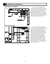
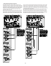
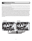
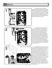
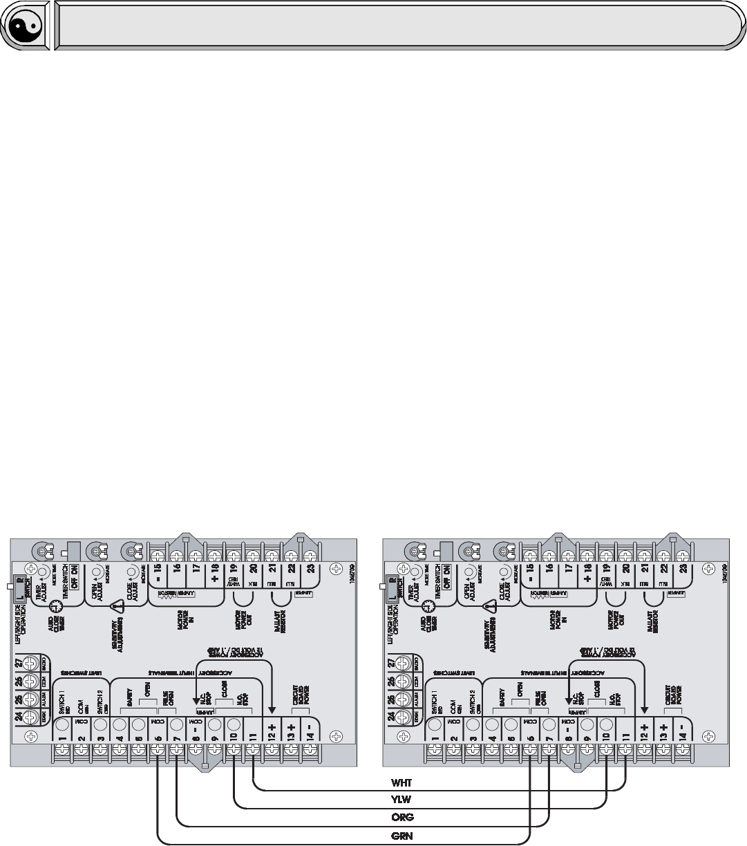
Connect 115 Volts AC to each SL920 gate operator. Connect the four Master/Second wires from the master circuit board
to the Second circuit board as shown below. Any operator can be used as either a master or a Second. Accessories can be
connected to the master or second operator.
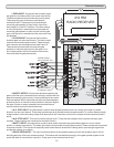
z Switch the Auto Close Timer switch to the OFF position on the Second circuit board. The Auto Close Timer switch on the
master circuit board may be switched either ON if the timer function will be used or OFF if the timer function will not be used
but the Second timer must always be switched OFF.
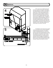
z If the chain is wrapped around the sprockets in the same manner on each operator (both chains under or both chains over
the drive sprocket) set the Right/Left Side Operation switch on the master circuit board to be the opposite of the way it is set
on the Second circuit board. If the chain wrapped around the drive sprocket on the master operator is the opposite of the way
it is wrapped around on the Second operator then set the Right/Left Side Operation switches the same on both operators.
The Right/Left Side operation switch is located on the circuit board. If the operators are working backwards, the Right/Left
Side Operation switches on both operators must be switched. The simplest way to know if the operators are working back-
wards is to turn the Auto Close Timer switch on the master circuit board to ON and see whether the timer works when the
gate is open or closed. The timer should work only when the gate is open. Another way to know if the operators are working
backwards is to try the gate sensitivity by applying pressure against the gate while the gate is opening or closing. If pressure
is applied while the gate is opening it should stop. If pressure is applied while the gate is closing it should reverse and go
open. If the gate responds to pressure in a way that is opposite of this then switch the Right/Left Side Operation switch on
both operators.
SL920 MASTER/SECOND
Master/Second Wiring
MASTER SECOND


