


16
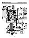
Wiring Diagrams, Button Controls
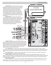
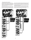
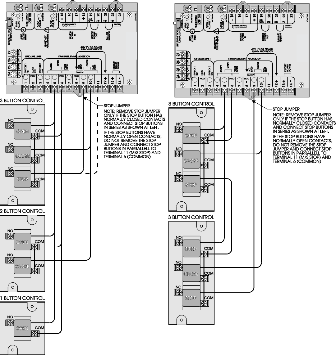
z One button, two button and three button controls may be
connected individually or together as shown below. Most button
controls have a common "buss bar" which connects the common
terminals of all buttons together so that only one common wire
needs to be run back to the gate operator control board. If this is
not the case, the common terminals of each button may be
connected together with wire.
z Connect the common terminal or terminals (COM) of the push
button control to the Common (terminal 6) on the gate operator
control board. Connect the Open button NO terminal of the push
button control to Open (terminal 5) on the gate operator control
board. Connect the Close button NO terminal of the push button control to Close
(terminal 10) on the gate operator control board. If the stop button has normally
closed contacts, connect the Stop button NC terminal to Stop (terminal 9) and
remove the stop jumper that is on terminals 8 & 9. If the stop button has normally
open contacts, connect the Stop button terminal NO to the NO Stop (terminal 11)
on the gate operator control board.
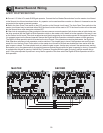
z If more than one push button control is used on one gate operator, connect
wires from the Open, Close and Common in parallel to the control board. If the
stop button has normally closed, contacts connect the stop buttons in series to
the control board. If the stop buttons have normally open contacts, connect the
stop buttons in parallel to NO Stop (terminal 11) on the control board.