


EDGE
EDGE
50-220 SAFETY SENSORS
50-220 SAFETY SENSORS
OR
OPEN (EXIT LOOP )
SINGLE BUTTON (SBC)
RESET
STOP
SHADOW LOOP
INTERRUPT LOOP
50-220 SAFETY SENSORS
CLOSE
EDGE
R93
D42
K2
D1
Ø
OPEN EDGE/
PHOTO
OPEN
PHOTO
CLOSE
PHOTO
Z22
P1
F2
MOV1
D1
Q12
U4
CONTROL
INPUTS
FORCE
TIMER TO
CLOSE
OFF MAX
OPEN
SINGLE BUTTON
RESET
STOP
SHADOW
INTERRUPT
CHGR
OVLD
CTRL PWR
CTRL
LOOP
INPUTS
D129
Z4
U3
D2
D44
C11
C13
C12
D16
F9
R1
Ø
1
R1
ØØ
K1
Q22
F3
K3
K4
R196
F1
Z12
GATE 2
ACCESSORY
POWER
ALARM
GATE 1
MAGR
SOL
GR
WH
YL
BL
RD
BR
GR
WH
YL
BL
RD
BR
F7
12 V
CTRL
OVLD
TIMER
RUNNING
GATE 2
SET
OPEN
LIMIT
SET
CLOSE
LIMIT
LEARN
LIMITS
DIAGNOSTIC
GATE 1
LEARN
XMITTER
LOCK /
ON OFF
PWR
C69
OFF MAX
J2
Ø
PWR
SINGLE BUTTON
AC PWR
/SOLAR
D8
D4
R9
R329
R27
MOV2
R4
C2
BIPART DELAY
LOCK
GND
Z1
R1
R2
K5
F12
Q9
R9
Ø
F8
Q6
Q1
J19
ACCESSORY
0VLD
R182
C1
Ø1
C75
C73
C72
C71
C7
Ø
C66 C65
C68
C33
F11
R186
R42
Ø
R423
J24 J23 3
Ø
A 32V
3
Ø
A 32V
J21
C64
R22
U2
J18
K6
JU1
JU2
DB1
D36
R184
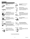
(optional)
Fault Alarm
Automatic Gate Lock
WHT
GRN
BRN
YEL
BLU
RED
WHT
GRN
BRN
YEL
BLU
RED
CTRL PWR
SOLAR PANEL
RED
RED
BLK
BLK
Gate 1 (Primary)
Gate 2 (Secondary)
RED
BLK
OPTIONAL GROUND ROD
OPTIONAL TRANSFORMER
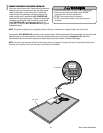
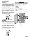
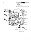
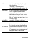
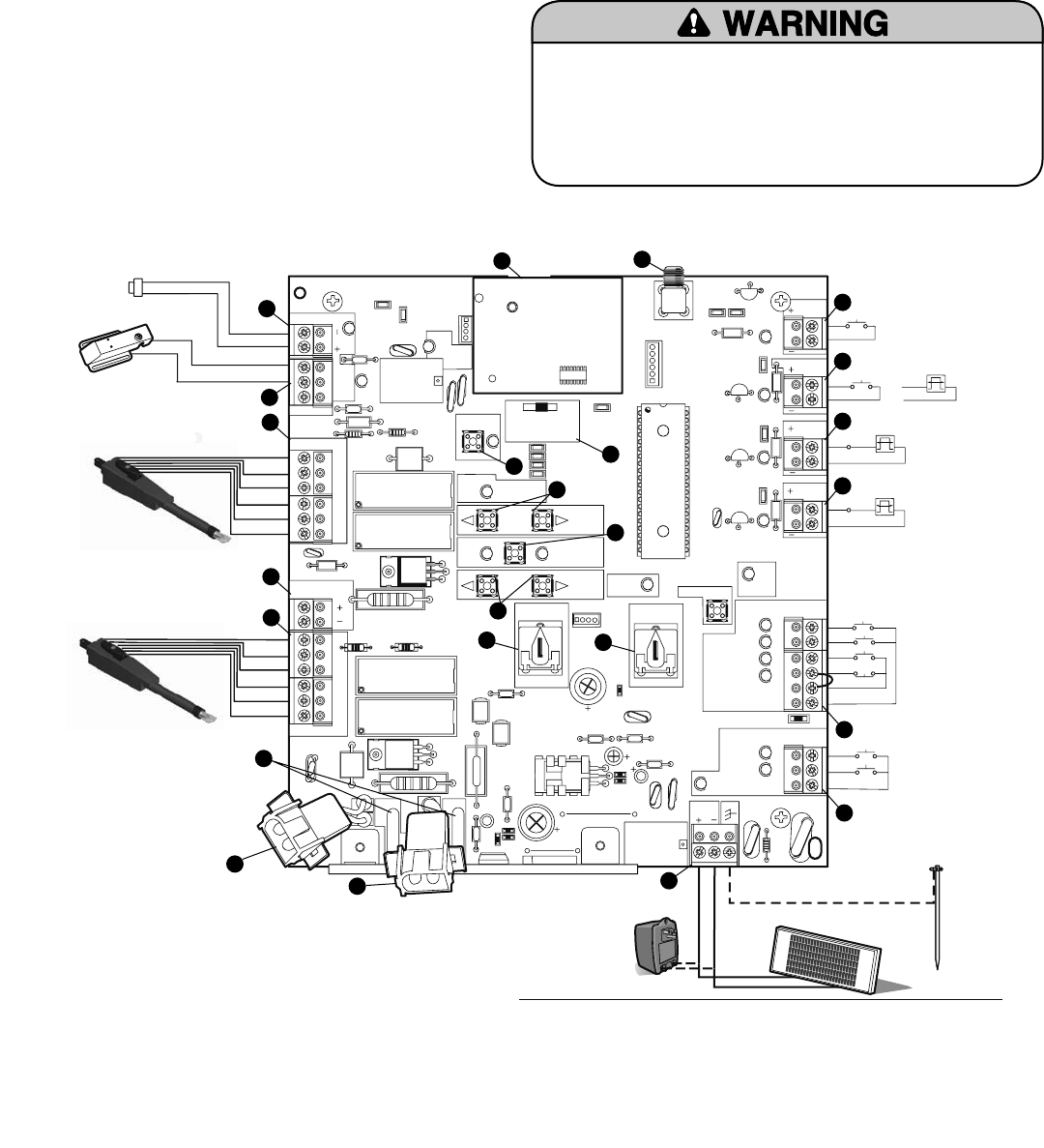
To protect against fire and electrocution:
• DISCONNECT power and battery BEFORE installing or servicing operator.
For continued protection against fire:
•
Replace ONLY with fuse of same type and rating.
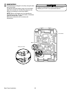
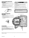
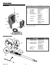
17. Learn Xmitter
18. Primary Gate Jog
19. Learn Limits
20. Secondary Gate Jog
21. Force
22. Timer To Close
23. Receiver Module
24. Fuses (20 Amp)
9. Gate 2
10. Accessory Power*
11. Gate 1
12. Lock (Solenoid/Maglock) Output*
13. Alarm Output*
14. Battery 1 Connector
15. Battery 2 Connector
16. Lock/BiPart Delay
1. Antenna Input
2. Close Edge*
3. Open Edge/Photo*
4. Open Photo*
5. Close Photo*
6. Control Inputs*
7. Loop Inputs*
8. AC PWR/SOLAR
15
24
8
7
14
NOTE: Batteries MUST
be connected to operate.
NOTE: 14.5 V output
on transformer.
*
6
*
5
*
4
*
3
*
2
*
9
21
19
17
16
18
22
20
10
12
*
13
*
*
11
1
23
*Class 2 circuit 15 V maximum output
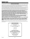
To protect against fi re and electrocution:
• DISCONNECT power and battery BEFORE installing or
servicing operator.
For continued protection against fi re:
• Replace ONLY with fuse of same type and rating.
Wiring Diagram
39 Operation and Maintenance