


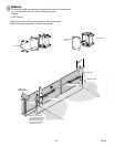
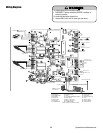
PROGRAMMING
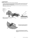
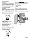
Program Limits
The limits are internal settings that indicate when the gates are in the fully open position and the fully closed position. For
proper functionality, the limits must be programmed during the installation process. The programming uses a combination
of buttons on the control board.
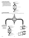
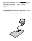
The specifi c buttons used for programming depends on which side of the gate the control box is mounted and how many
operators the installation includes. Refer to pages 11 and 13 to determine if the gate is Left- or Right-handed.
If a mistake is made during programming press the RESET button on the outside of the control box to start over.
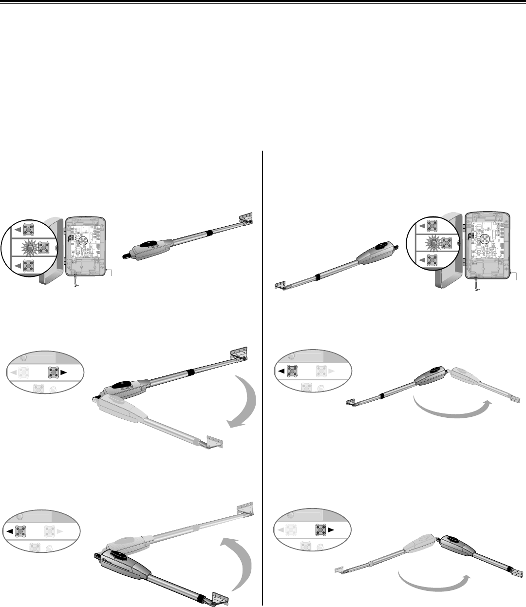
SINGLE ARM LEFT-HAND SIDE SINGLE ARM RIGHT-HAND SIDE
NOTE: The programming can be exited at any time by pressing the RESET button. The programming times-out automatically after 60
seconds of inactivity.
33 Programming
Z22
R91
CLOSE
EDGE
R94
R92
R93
L1
R1
R2
Z1
K5
K6
K2
F3
10A 32V
D1
Ø
OPEN EDGE/
OPEN EDGE/
PHOTO
OPEN
PHOTO
CLOSE
PHOTO
R227
R2
Ø
7
Z2
Ø
R223
P1
Z9
Z8
F2
F6
D4
D2
R9
C64
JMPR1
R224
U4
CONTROL
INPUTS
FORCE
TIMER TO
CLOSE
OFFMAX
OPEN
SINGLE BUTTON
RESET
STOP
SHADOW
INTERRUPT
CHGR
OVLD
COM
COM
COM
FUSE
OPEN
LOOP
INPUTS
POWER
BATT 1BATT 2
F1 20A 32V
R35
D9
Z3
Z4
U3
D1
F5
C11
C13
C12
D15
C2R4
R1
Ø
1
R1
ØØ
R9
Ø
Q9
K1
R196
Q22
D8
K3
K4
D21
D22
C4
ACCESSORY
OVLD
D6
JMPR2
MOV1
MOV2
DB1
U2
Z12
24 VAC/
SOLAR
INPUT
GATE 2
ACCESSORY
POWER
MAGLOCK
ALARM
GATE 1
C
C
NC
NO
NO
GRN
WHT
YEL
BLU
RED
BRN
GRN
WHT
YEL
BLU
RED
BRN
F4
10A 32V
F7
24V
COM
OVLD
TIMER
RUNNING
GATE 2
SET
OPEN
LIMIT
SET
CLOSE
LIMIT
LEARN
LIMITS
DIAGNOSTIC
GATE 1
J4
LEARN
XMITTER
MAGLOCK
ON OFF
D4
D2
U4
SET
OPEN
LIMIT
RESET
BUTTON
RESET
BUTTON
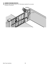
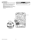
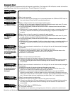
LEARN LIMITS button
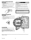
Press the Gate 1 right button to move gate to the desired
OPEN position. When gate is in the desired position, press
the LEARN LIMITS button again. Control board will beep.
Press the Gate 1 left button to move gate to the desired
CLOSED position. When gate is in the desired closed
position, press the LEARN LIMITS button again.
Press the Gate 1 left button to move gate to the desired
OPEN position. When gate is in the desired position, press
the LEARN LIMITS button again. Control board will beep.
When the SET CLOSE LIMIT LED blinks, press the
Gate 1 right button. When gate is in the desired closed
position, press the LEARN LIMITS button.
The control board beeps and the SET OPEN LIMIT and SET CLOSE LIMIT LEDs stop blinking, programming is
now complete. (If the SET OPEN LIMIT LED continues to blink, repeat programming. If the problem continues, see
Troubleshooting section.)
Test the limits by pressing the SBC to open and close the gate.
Z22
R91
CLOSE
EDGE
R94
R92
R93
L1
R1
R2
Z1
K5
K6
K2
F3
10A 32V
D1
Ø
OPEN EDGE/
OPEN EDGE/
PHO T O
OPEN
PHO T O
CLOSE
PHO T O
R227
R2
Ø
7
Z2
Ø
R223
P1
Z9
Z8
F2
F6
D4
D2
R9
C64
JMPR1
R224
U4
CONTROL
INPUTS
FORCE
TIMER TO
CLOSE
OFF MAX
OPEN
SINGLE BUTTON
RESET
STOP
SHADOW
INTERRUPT
CHGR
OVLD
COM
COM
COM
FUSE
OPEN
LOOP
INPUTS
POWER
BATT 1 BATT 2
F1 20A 32V
R35
D9
Z3
Z4
U3
D1
F5
C11
C13
C12
D15
C2 R4
R1
Ø
1
R1
ØØ
R9
Ø
Q9
K1
R196
Q22
D8
K3
K4
D21
D22
C4
ACCESSORY
OVLD
D6
JMPR2
MOV1
MOV2
DB1
U2
Z12
24 VAC/
SOLAR
INPUT
GATE 2
ACCESSORY
POWER
MAGLOCK
ALARM
GATE 1
C
C
NC
NO
NO
GRN
WHT
YEL
BLU
RED
BRN
GRN
WHT
YEL
BLU
RED
BRN
F4
10A 32V
F7
24V
COM
OVLD
TIMER
RUNNING
GATE 2
SET
OPEN
LIMIT
SET
CLOSE
LIMIT
LEARN
LIMITS
DIAGNOSTIC
GATE 1
J4
LEARN
XMITTER
MAGLOCK
ON OFF
D4
D2
U4
D9
Z3
Z4
U3
D1
D6
OFF
SET
OPEN
LIMIT
EN
T
RESET
BUTTON
SET
CLOSE
DIAGNOSTIC
GATE 1
SET
CLOSE
DIAGNOSTIC
GATE 1
SET
CLOSE
DIAGNOSTIC
GATE 1
SET
CLOSE
DIAGNOSTIC
GATE 1
With the gate in the CLOSED position, press the LEARN
LIMITS button (SET OPEN LIMIT LED will blink).
With the gate in the CLOSED position, press the LEARN
LIMITS button (SET OPEN LIMIT LED will blink).
LEARN LIMITS button
PROGRAM OPEN
PROGRAM CLOSE
PROGRAM OPEN
PROGRAM CLOSE