


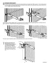
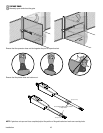
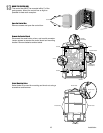
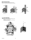
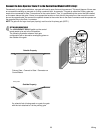
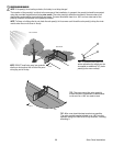
Connect the Gate Operator (Gate 2) to the Control Box (Model LA412-S Only)
Occasionally in dual gate installations, one gate will need to open fi rst and close second. This would happen if there was
an ornamental overhang on one gate or if using a solenoid lock, for example. This gate is called the Primary gate and
needs to be connected to Gate 1 connections on the control board. Thus, it is preferred that the control box be installed
on the same side as this gate. If there is no appropriate location on that side for the control box, then mount the control
box on the opposite side, but connect the operator closest to the control box to the Gate 2 connector and the operator on
the opposite side to the Gate 1 connector.
NOTE: The gate with the longer travel span (opening) must be set as the primary gate (GATE 1).
4
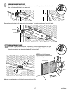
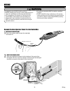
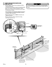
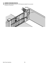
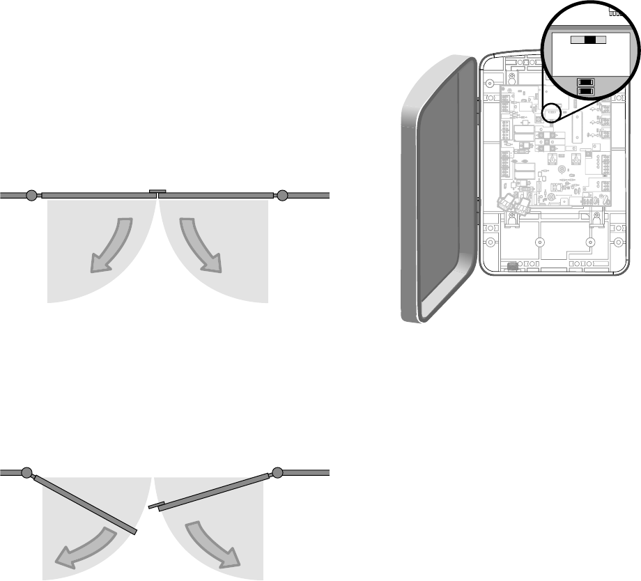
SET THE LOCK/BIPART DELAY
The LOCK/BIPART DELAY switch on the control
board needs to be set to the ON position.
The following illustration shows a dual gate
confi guration with a decorative overlapping piece on
the outside of the gate.
Control Box
18
18
R93
R93
D42
D42
K2
K2
D1
D1
Ø
Z22
Z22
P1
P1
F2
F2
MOV1
MOV1
D1
D1
Q12
Q12
U4
U4
D129
D129
Z4
Z4
U3
U3
D2
D2
D44
D44
C11
C11
C13
C13
D16
D16
F9
F9
R1
R1
Ø
1
R1
R1
ØØ
ØØ
K1
K1
Q22
Q22
F3
F3
K3
K3
K4
K4
R196
R196
F1
F1
Z12
Z12
GATE 2
GATE 2
GR
GR
WH
WH
YL
YL
BL
BL
RD
RD
BR
BR
F7
F7
24V
24V
GATE 2
GATE 2
SET
SET
OPEN
OPEN
LIMIT
LIMIT
SET
SET
CLOSE
CLOSE
LIMIT
LIMIT
LEARN
LEARN
LIMITS
LIMITS
GATE 1
GATE 1
C69
C69
J2
J2
Ø
D8
D8
D4
D4
R9
R9
R329
R329
R27
R27
MOV2
MOV2
R4
R4
C2
C2
Z1
Z1
R2
R2
K5
K5
F12
F12
Q9
Q9
R9
R9
Ø
F8
F8
Q6
Q6
Q1
Q1
C75
C75
C73
C73
C72
C72
C71
C71
C7
C7
Ø
C66
C66
C65
C65
C68
C68
C33
C33
F11
F11
R42
R42
Ø
R423
R423
J24 J23 3
J24 J23 3
Ø
A 32V
A 32V
3
3
Ø
A 32V
A 32V
J21
J21
30
30
30
30
C64
C64
R22
R22
U2
U2
J18
J18
K6
K6
JU1
JU1
JU2
JU2
DB1
DB1
D36
D36
C71
C7Ø
ON
OFF
LOCK/
BIPART DELAY
18
R93
D42
K2
D1
Ø
Z22
P1
F2
MOV1
D1
Q12
U4
D129
Z4
U3
D2
D44
C11
C13
D16
F9
R1
Ø
1
R1
ØØ
K1
Q22
F3
K3
K4
R196
F1
Z12
GATE 2
GR
WH
YL
BL
RD
BR
F7
24V
GATE 2
SET
OPEN
LIMIT
SET
CLOSE
LIMIT
LEARN
LIMITS
GATE 1
C69
J2
Ø
D8
D4
R9
R329
R27
MOV2
R4
C2
Z1
R2
K5
F12
Q9
R9
Ø
F8
Q6
Q1
C75
C73
C72
C71
C7
Ø
C66C65
C68
C33
F11
R42
Ø
R423
J24 J23 3
Ø
A 32V
3
Ø
A 32V
J21
30
30
C64
R22
U2
J18
K6
JU1
JU2
DB1
D36
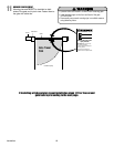
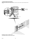
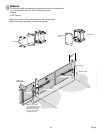
Outside Property
Primary Gate - Connect to Gate 1 Connector on
Control Board.
Primary Gate
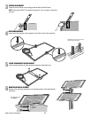
Outside Property
If a solenoid lock is being used on a gate, the gate
with the lock attached to it is the primary gate.
23 Wiring