


PAGE 7
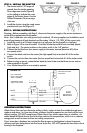
STEP 9: WIRING INSTRUCTIONS
Warning: Before proceeding with Step 9, disconnect the power supply at the service entrance or
switch off the appropriate circuit breaker.
Note: Use 3-conductor wire with ground (not furnished). All wiring supplies and installations must
meet all requirements of local electrical and fire codes. Wire to 115-120V, 60 Hz current only.
1. Install the switch in a UL-listed wiring box in a wall near the fan (typically in a hallway).
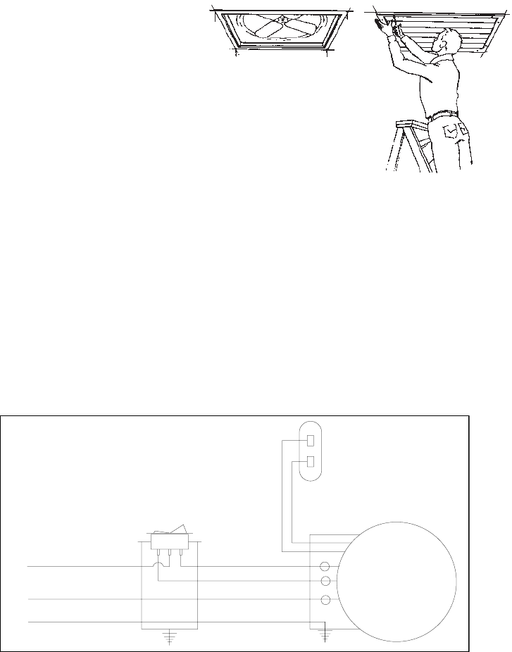
2. Refer to Figure 10 to wire all models. Cool Attic Whole House Fans have two fixed speeds
(high and low). The center position on the rocker switch is the “off” position.
3. Connect the hot line from your power supply to the center terminal (terminal #2) of the
two-speed switch.
4. Connect the black wire from the motor (the high-speed line) to terminal #3 of the rocker
switch.
5. Connect the red wire from the motor (the low-speed line) to terminal #1 of the rocker switch.
6. Before turning on power, rotate the fan blade by hand to be sure that there are no tools or
other materials in its path.
7. Your Whole House Fan is now ready to operate.
OPERATING INSTRUCTIONS
Whole House Fans cool your home by pulling in fresh, cooler air from the outside through open
windows and doors. In a two-story home, windows should be opened on one level only for most
efficient cooling. DO NOT operate your Whole House Fan without open doors or windows. An
added benefit of Whole House Fans is that they reduce attic temperatures, which in turn, reduces
energy costs as well as wear and tear on roofing components.
If your home has a fireplace, be sure that the flue damper on the fireplace is closed to prevent
chimney soot from being drawn into the house by the fan. DO NOT operate the fan when a fire is
burning in the fireplace.
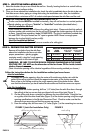
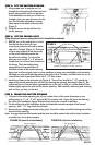
1. The shutter itself is 7/8” larger all
around than the shutter opening.
Draw alignment marks (Figure 8)
on the ceiling to indicate the outer
edges of the shutter frame. Use the
Shutter Dimension Chart on page
4 for size.
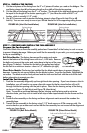
FIGURE 8 FIGURE 9
FAN
MOTOR
GROUND
WHITE
RED (LOW)
BLACK (HI)BLACK
WHITE
GREEN
HI-OFF-LOW
1 2 3
BROWN
BROWN
CAPICITOR ATTACHED
AT FACTORY
INCOMMING POWER
SUPPLY 120V / 60 HZ
RED - LOW SPEED
BLACK - HIGH SPEED
WHITE - COMMON
FIGURE 10
STEP 8: INSTALL THE SHUTTER
2. Install the shutter using the wood screws
provided with your fan (Figure 9).