78-0013-4441-1-D 11
3M
™
One Pass Mini Fiber Pathway
15.0 Fiber Repair
15.1 Ensure that the root cause for service interruption is
damaged 900 µm.
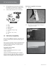
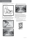
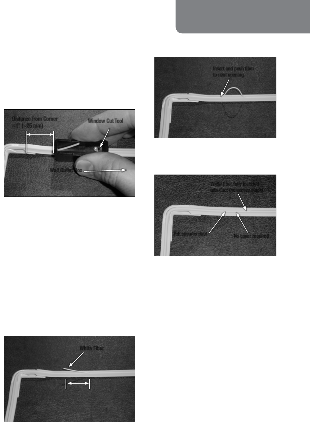
15.2 Working away from the Wall Outlet, make small
window cuts using the Window Cut Tool at every
other corner or turn.
Note: Additional window cuts at other corners may be
made if needed.
Window Cut Tool
Wall Outlet Box
Distance from Corner
~1" (~25 mm)
15.3 Cut connectors/fusion splice sleeves from the ends
of the fiber stored inside the Wall Outlet and Point-
of-Entry (POE) Cover of the damaged 900 µm fiber.
Pull existing (gray) 900 µm fiber from installed duct
and discard per company practice.
Note: If pulling 900 µm is difficult the window cuts made
in step 2 may be used as intermediate pull back locations.
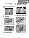
15.4 Wrap 2'-4' (600-1200 mm) of the new white
900 µm fiber into the Wall Outlet to create enough
slack for connector termination and begin pushing it
into the duct.
Note: Keep new 900 µm off of the floor and clean as it
is pushed into the duct to reduce floor debris from being
carried into the duct.
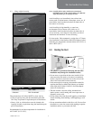
15.5 When the new white 900 µm fiber comes through
each window cut, pull gently at that point to remove
slack.
White Fiber
Cut Length:
~1" (~25 mm)
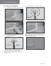
15.6 Begin pushing 900 µm out the other end of the
window cut until the next window cut is reached.
Insert and push fiber
to next opening
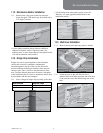
15.7 Repeat steps 5 and 6 until the new fiber is fully
inserted into the duct, through provided furcation
tubing, and into the Point-of-Entry (POE) Box. The
fiber should be flush with each window cut.
White fiber fully inserted
into duct (no excess slack)
No cover required
Tab secures duct
15.8 Terminate new 900 µm fiber per company practice.


