Memory Locations and Replacement Procedures
Matrix DFE-Gold Series Modules Hardware Installation Guide B-5
Memory Locations and Replacement Procedures
IntheeventthattheDualIn‐lineMemoryModule(DIMM)orDRAMSingleIn‐line
MemoryModule(SIMM)(FLASHmemory)needstobereplaced,thefollowingsections
describehowtoaccess,locateandreplacethesememorymodules.
Ifyouhavequestionsconcerningthereplacementofeithermemorymodule,referto
“GettingHelp”onpage xviiifordetailsonhowtocontactEnterasys Networks.
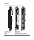
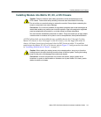
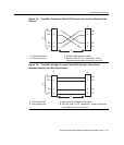
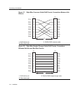
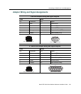
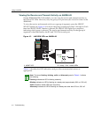
Location of DIMM and DRAM SIMM Memory Modules
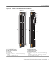
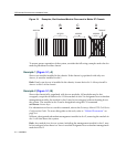
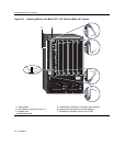
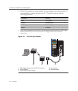
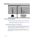
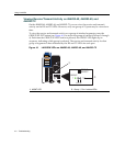
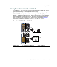
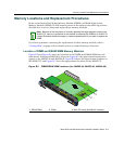
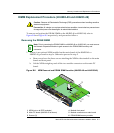
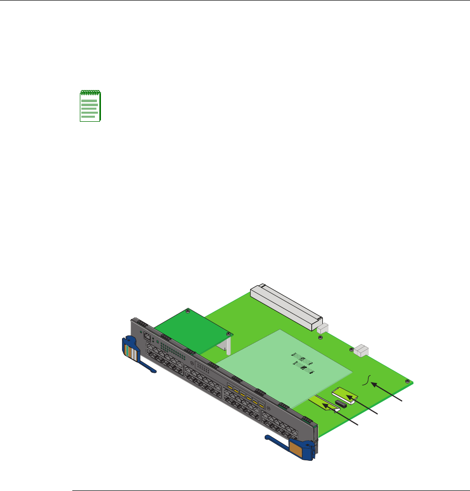
Figure B‐5andFigure B‐6showthelocationsoftheDIMMandDRAMSIMMoneach
mainboard.Although4H4282‐49 isshowninFigure B‐5,theapproximatelocationalso
appliestothe4H4283‐49and 4H4284‐49. Figure B‐6showstheapproximatelocationson
the4H4203‐72,andFigure B‐
7showstheapproximatelocationsonthe4H4202‐72.
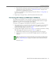
Note: Because of the complexity of correctly replacing the large daughter board on the
4H4202-72, there is no procedure in this manual for replacing the DIMM on a 4H4202-72.
Contact Enterasys Networks support or nearest representative if you need to replace the
DIMM.
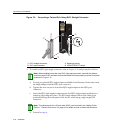
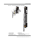
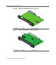
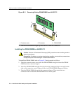
Figure B-5 DIMM/DRAM SIMM Locations (for 4H4282-49, 4H4283-49, 4H4284-49)
1 DRAM SIMM 2 DIMM 3 Main PC board (4H4282-49 is shown)
4H4282-49
F
AST ENET
DFE
1
2
3
4
5
6
➀
➁
➂