Introduction
Before You Begin
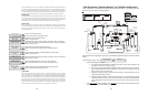
What’s Included
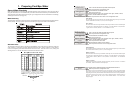
Before attempting to install the Aqua Logic system, check that the following components have been
included in the package:
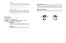
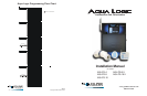
Aqua Logic Electronics Unit
(3) Temperature sensors with 15 ft. (5m) cable, hose clamp
Aqua Logic Expansion Unit (PS-16 only)
What’s NOT Included
Some of the additional items that you may need to complete an installation include:
Circuit breakers
None are included with control—see page 12 and inside of door for suitable breakers
Wire
4-conductor cable (electronics unit to remote display/keypad)
Wire/conduit for 100A service from main panel to Aqua Logic
Wire/conduit for filter pump and other high voltage loads
Wire for bonding
Miscellaneous
Utility electrical outlet and weatherproof cover (for mounting on side of Aqua Logic)
Mounting hardware (screws, etc.) for mounting Aqua Logic and remote display/keypad
Valves (use standard Hayward, Pentair/Compool, or Jandy valves)
Additional valve actuators
Accessory Products - Order Separately
AQL-CL Chlorination kit
AQL2-Wx-PS-4 Wired Remote Display (see note 1)
AQL2-Wx-PS-8 Wired Remote Display (see note 2)
AQL2-Wx-PS-16 Wired Remote Display (see note 3)
AQL2-POD Handheld wireless remote control
AQL2-Wx-RF-PS-4 Wireless Wallmount Remote Control(see notes 1, 4, 5)
AQL2-Wx-RF-PS-8 Wireless Wallmount Remote Control(see notes 2, 4, 5)
AQL2-Wx-RF-PS-16 Wireless Wallmount Remote Control(see notes 3, 4, 5)
AQL2-Tx-RF-PS-4 (x=W/B) Wireless Table Top Remote Control, specify color - white or black (see notes 1,4,5)
AQL2-Tx-RF-PS-8 (x=W/B) Wireless Table Top Remote Control, specify color - white or black (see notes 2,4,5)
AQL2-Tx-RF-PS-16(x=W/B) Wireless Table Top Remote Control, specify color - white or black (see notes 3,4,5)
AQL-SS-6B-x (x=W/G/B) Wired Spa Side 6 Function Remote Control, 150ft cable, spec. color (white, gray or black)
AQL-SS-D-x (x=W/G/B) Wired Spa Side 8 Function Remote Control, 150ft cable, spec. color (white, gray or black)
AQL2-SS-RF Wireless Spa Side Remote Control (see note 4)
AQL2-BASE-RF Base Station
AQL-DIM Light Dimmer Relay
GVA-24 Valve Actuator
V&A-xx Valve & Actuator (xx=1P (1.5” pos. seal), -2P (2” pos. seal))
Notes: 1. for use with PS-4 model only
2. for use with PS-8 model only
3. for use with PS-16 model only
4. requires base station AQL2-BASE-RF
5. 9V wall plug-in power supply included
1
38
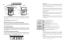
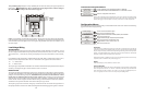
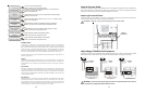
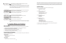
Heater Checkout
Follow these instructions to verify that the Aqua Logic is properly controlling the heater.
1. Check that the Aqua Logic is calling for the heater to turn on as indicated by the “Heater” LED being
illuminated. If the “Heater” LED is illuminated, go directly to step 2; if not, then check the following:
• The heater is enabled (Configuration Menu/Heater Config.).
• The heater temperature setting is at least 2ºF greater than the water temperature (Settings Menu /
Pool Heater & Spa Heater).
• The filter pump is running.
• If the pool has solar heat and the solar priority feature is enabled (Configuration Menu/Solar
Config) then solar must be off in order for the heater to fire. The easiest way to force solar off is to
go to the Settings Menu / Pool Solar & Spa Solar and temporarily lower the temperature settings
below the current water temperature.
2. Check that the heater is running. If not, then check:
• Power is supplied to the heater.
• The Aqua Logic control output is properly connected to the heater control (see ”Heater Control”
wiring, page 15).
• Some heaters also have internal switches or jumpers that have to be set correctly for remote
control operation—refer to the heater manual and also “Heater Control” (page 15).
• Heater is turned on (“Kill Switch” is in the “ON” position).
• If a heater bypass valve is installed, check that water is flowing through the heater.
• The heater temperature setting is set as high as possible (usually 104ºF/40ºC). Also note that
some heat pumps actually have be set to the lowest possible temperature.
3. Once the heater is running, you can verify the “heater cooldown” feature (optional - see Configuration
Menu/Heater Config.) is operating properly:
• Press the “Filter” button once (for 2 speed pumps, this may require 2 pushes of the “Filter”
button).
• The heater should turn off (“Heater” LED off) and the “Filter” LED will flash to indicated heater
cooldown is active.
• The display will periodically indicate that the filter pump is on for heater cooldown and show the
minutes remaining.
• The pump will automatically turn off at the end of the 5 minute heater cooldown period.
For more detailed instructions on control and operation of the Aqua Logic system, refer to the Operation
Manual.
Service Mode
Service mode disables all automatic control operation and is intended to be used when servicing the pool
system. To enter service mode, push the SERVICE button once on the main unit keypad. This will initially
turn all outputs off and then allow you to turn outputs on/off manually at the main display (only). In service
mode, the buttons on the optional remote display/keypad and the optional spa side remote will turn
outputs off, but will not turn any output on. Heater control outputs and solar control outputs are prevented
from turning on if the water temperature exceeds 104ºF (40ºC).
Pushing the SERVICE button again will enter a timed service mode. Service operation as described
above will continue for 3 hours, then automatically return to normal operation.
Push the SERVICE button once more to exit out of Service mode.