2. The water sensor should be installed on the pool loop prior to the heater(s) and will display the
pool temperature whenever the “Pool Filter” pump is running.
3. The solar sensor should be installed on the spa loop prior to the heater(s) and will display the spa
temperature whenever the “Spa Filter” pump is running.
4. Solar heater control is NOT available for dual equipment systems.
5. The Aqua Logic can be programmed to accommodate spillover if desired. Note that spillover
operation will be automatically suspended whenever the spa filter pump is turned on.
6. The chlorinator cell and flow switch must be installed in the heater return path. If spillover is
enabled, then the Aqua Logic can chlorinate both the pool and spa (during spillover operation).
Otherwise, the Aqua Logic will only chlorinate the pool when the spa does not control the heater(s)
and the spa sanitization will have to be handled manually.
7. If any water feature or pressure side cleaner boost pumps are used, be sure to enable the “interlock”
feature (see “Configuration Menu” for details) to ensure that the pumps operate only when the
“Pool Filter” pump is on and the system is in the “pool only” operating mode.
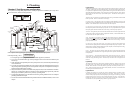
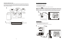
8. The plumbing diagram on page 11 is intended to be used as a general guideline and is not a
complete plumbing schematic for the pool.
9. When using the wireless spa-side remote control (AQL-SS-RF), the “POOL” button will position
the valves for Pool mode and the “SPA” button will position the valves for Spillover mode.
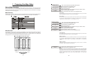
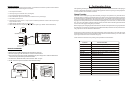
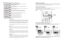
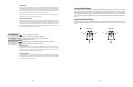
Turbo Cell (supplied with AQL-CL chlorination kit)
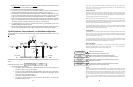
The Turbo Cell (used for chlorine generation) should be plumbed AFTER the filter and heater. If installed
on a pool/spa combination system, the cell should be plumbed BEFORE the pool/spa return valve in order
to allow proper chlorination of both the pool and the spa. Refer to plumbing diagram below:
The cell may be mounted vertically or horizontally, and water can move in either direction through the cell.
Install using the 2" unions provided. Tighten unions BY HAND for a watertight seal. For systems with
1½“ plumbing use adaptors (provided by installer).
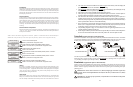
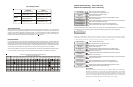
Flow Switch (supplied with AQL-CL chlorination kit)
The flow switch must be plumbed in the same section of plumbing as the Turbo Cell. The flow switch is a
safety device that ensures that water is flowing through the cell before the Aqua Logic starts to generate
chlorine. Failure to properly install the flow switch can result in explosive gases accumulating in the pool
plumbing system.
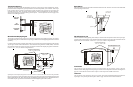
IMPORTANT: There must be at least a 12" (30cm) straight pipe run before (upstream)
the flow switch. If the switch is plumbed after the cell, the cell can by counted as the 12" (30cm)
of straight pipe.
IMPORTANT: To ensure proper operation, verify that the arrow on the flow switch points
in the direction of water flow.
12
12”
min
Flow switch before cell
Flow switch after cell
Flow Monitor
This feature will help protect the filter pump from damage due to no flow. When used with a
Goldline flow switch, the Aqua Logic monitors the state of water flow when the filter pump is
on. If no flow is detected for more than 15 minutes, the Aqua Logic will shut down the pool
pump and the “Check System” LED will indicate an error. The error will be cleared the next
time the pump is turned on.
Freeze Protection
Freeze protection is used to protect the pool and plumbed equipment against freeze damage.
If freeze protection is enabled and the AIR temperature sensor falls below the freeze thresh-
old (see below), the Aqua Logic will turn on the filter pump to circulate the water. If “Pool and
Spa” is selected in the Pool/Spa sub-menu (see page 24), the valves will also alternate
between the pool and spa every 30 minutes and the filter pump will turn off while the valves
are turning. The chlorinator will not operate if freeze protection is the only reason the pump
is running.
Freeze Protection Temperature
Select the temperature to be used for freeze protection. Temperature is adjustable from 33ºF
- 42ºF (1ºC - 6ºC). 38ºF (3ºC) is default. This threshold will be used for all outputs that have
freeze protection enabled.
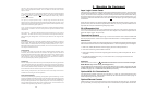
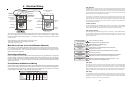
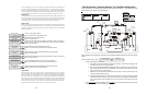
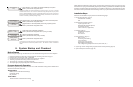
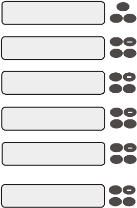
NOTE: Heater1 and Heater2 configuration are identical. If Heater2 is enabled then Valve4 will automatically be
disabled due to the fact that they use the same output relay and only 1 function can be assigned to that relay.
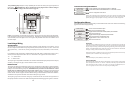
Heater1 Config.
+ to view/change
Heater1
Disable
Heater1 Cooldown
Disabled
Heater1 Extend
Disabled
Push to access heater options
Toggle between Enabled and Disabled (default) Heater 1
Toggle between Enabled and Disabled (default) Heater 1 Cooldown
Toggle between Enabled and Disabled (default) Heater 1 Extend
Move to previous/next configuration menu
Move to next menu item or previous/next configuration menu
Move to next menu item
Move to previous/next configuration menu
if “Heater1” is enabled
if “Heater1” is enabled
if “Heater1” is enabled
+
+
>
>
>
>
>
>
>
>
Heater1 Name
Gas Heater
Rotates between all available names
Move to next menu item
+
>
>
Allow Low Speed
Disabled
Toggle between Enabled and Disabled (default)
next menu item or previous/next configuration menu
if “Heater1” is enabled and
2-speed filter pump is enabled
Heater1
If the heater is “Enabled”, the heater relay will turn on when the water temperature is less
than the desired temperature setting and the filter pump is running. The desired temperature
is in the “Settings Menu”. If applicable, the homeowner will be prompted to enter separate
“pool” and “spa” settings. Depending on the position of the pool/spa suction valves, the
proper temperature setting will be used.
Heater Name
The Aqua Logic allows you to assign any one of a number of names (e.g. “Gas Heater, Heat
Pump, etc.) to each of the heater control functions. This will make the Aqua Logic much
more user friendly to the homeowner when they want to turn various heaters on or off or set
27