


FR587W-INS-LAB-RevC13: Deluxe Extra-Wide Clinical Care Recliner Assembly and Operating Instructions
15
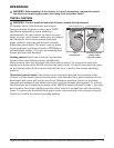
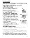
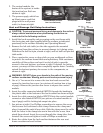
2. The control module, the
brains of the system, is inside
the junction box. Both are
shown at right.
3. The power supply, which has
an 8-foot power cord that
plugs into the wall power
outlet, is shown at right.
Heat and Massage Unit Setup Instructions
1. Install the back assembly and gas spring on the seat frame with
the clevis pins and clips supplied with the recliner as indicated
previously in the recliner Assembly and Operating Manual.
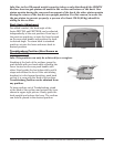
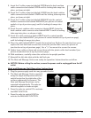
2. Remove the left side table (on the side opposite the mounted
switch box) from the recliner to prevent damage to it during setup:
Withdraw the ball lock pin, shown at right, and set ball lock pin and
table aside.
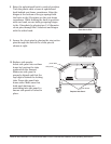
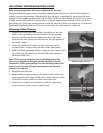
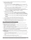
3. Place a protective cover or drop cloth on your workbench or oor
to protect the recliner frame nish and upholstery. With assistance,
carefully roll the recliner and rest it on its left side to provide
access to the seat bottom, as shown at right. If desired, for better
access, you may roll the recliner completely upside down. Carefully
extend the footrest partway for access to the components, as
shown at right.
4. Use a
1
/4" hex wrench to remove the two hex head screws that
secure the junction box cover (see picture of junction box at top
of page). Remove the junction box cover to expose the control
module.
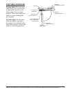
5.
Insert the cable connector labeled SWITCH through the bushing in
the plastic skirt at the bottom of the back cushion as shown at right.
6. Insert the cable connector labeled SWITCH into the control module
connector also labeled SWITCH (see picture of control module at
top of page) until its locking tab snaps into place.
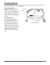
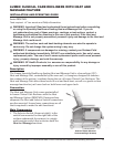
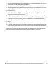
7. See picture at right. Use Phillips screwdriver to remove the screw
that secures the cushioned cable clamp. Remove the clamp and
place it around the switch box cable. Slide the clamp over the cable
until the holes in the clamp tabs are in line with the screw, then
pinch them closed. Insert the screw through the clamp tabs, then
reinstall the screw and tighten it with a Phillips screwdriver.
8. Route the cables from the back cushion between the rear seat
frame crossbar and seat bottom.
Control Module (Junction
Box Cover Removed)
Junction Box Power
Supply
Secure Switch Box
Cable Clamp
Insert Cable
Connector Labeled
SWITCH
Through Bushing
Roll Recliner
onto its Left Side
Remove
Left Side Table
ball lock
pin
left
side table
switch box cable
clamp
clamp tabs
screw