


24
SERVICING INSTRUCTIONS
REPLACING PARTS
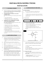
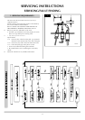
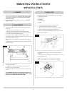
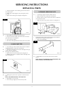
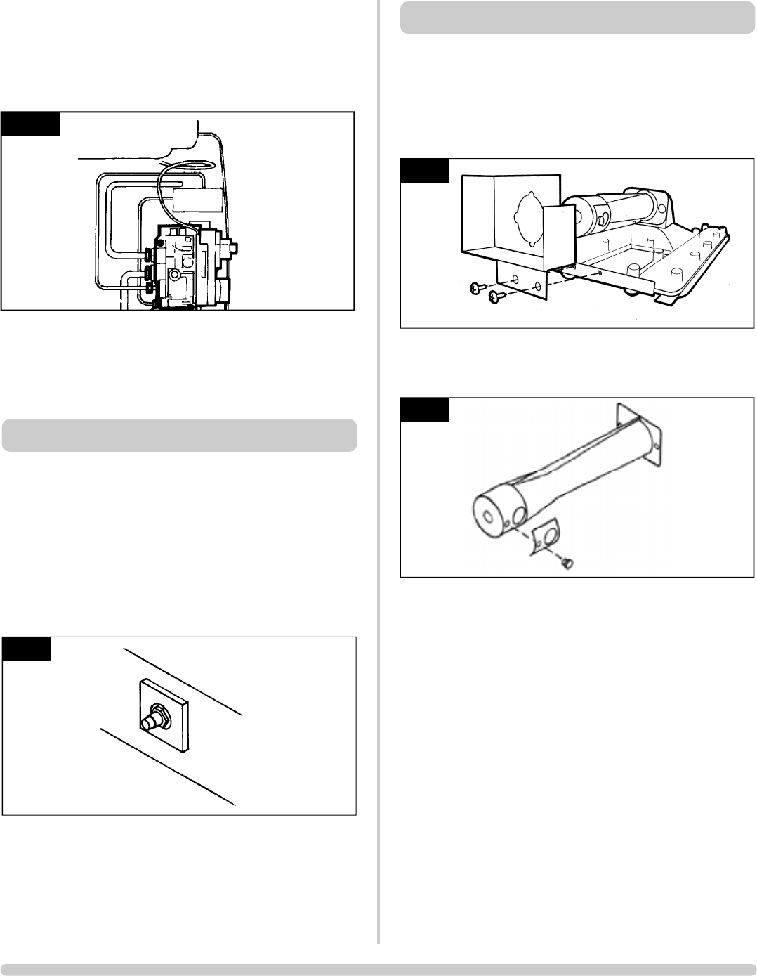
• Undo the magnetic valve-retaining nut from the back of
the control valve
• Gently tap out the magnetic valve and replace with a
new unit
• Replace the retaining nut and tighten, Diagram 13
7.2 • Reassemble the interrupter block and leads
• Secure the thermocouple connection at the rear of the
gas control (Do not overtighten)
• Turn on the gas supply
• Check the entire pipework and valve joints for any leaks
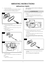
8.1 • Turn off the gas at the isolation device. Refer to Section
2, Replacing Parts to remove the main burner
8.2 • Undo the compression nut from the feed pipe at the gas
control under the appliance
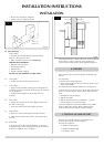
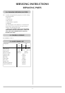
8.3 Working from inside the firebox:
• Remove the lock nut from the injector, Diagram 14
• Withdraw the injector complete with the feed pipe from
under the appliance
8.4 • Holding the injector with a spanner to undo the feed
pipe
NOTE: THE ORIENTATION OF THE INJECTOR.
8.5 • Reassemble in reverse order
• Turn on the gas supply and check for any leaks
AR0918
14
8. MAIN INJECTOR
13
AR0943
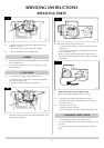
9.1 • Turn the gas supply off at the isolation device
• Refer to Section 2 to remove the main burner
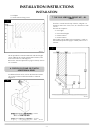
• Remove the two screws on the burner skin to detach the
cover from the venturi
• Slide the venturi cover off the venturi as in Diagram 15
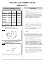
• Change the aeration plates to those stated in the technical
specification for the gas for this product
• Refer to the databadge
9.2 • Reassemble in reverse order with correct aeration
plate(s).
NOTE: EVEN IF NO AERATION PLATE IS REQUIRED, THE
SMALL SCREW(S) MUST BE REPLACED.
AR0619
16
AR1608
15
9. PRIMARY AERATION PLATE