


13
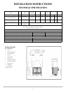
INSTALLATION INSTRUCTIONS
INSTALLATION
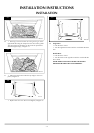
• Remove the remnant of cardboard
• File the newly cut edges to smooth
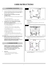
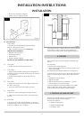
3.5 External Fixings
From outside:
• Push the flue assembly through the hole until the
terminal is flat against the wall
• Make sure the terminal is vertical NOTE ITS
ORIENTATION, DIAGRAM 3
• Mark the four fixing holes
• Remove the terminal
• Drill the holes
• Fill with supplied rawlplugs
DO NOT FIX THE TERMINAL AT THIS STAGE
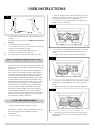
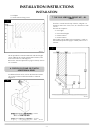
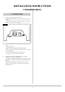
3.6 From inside:
• Position the stove observing all clearances
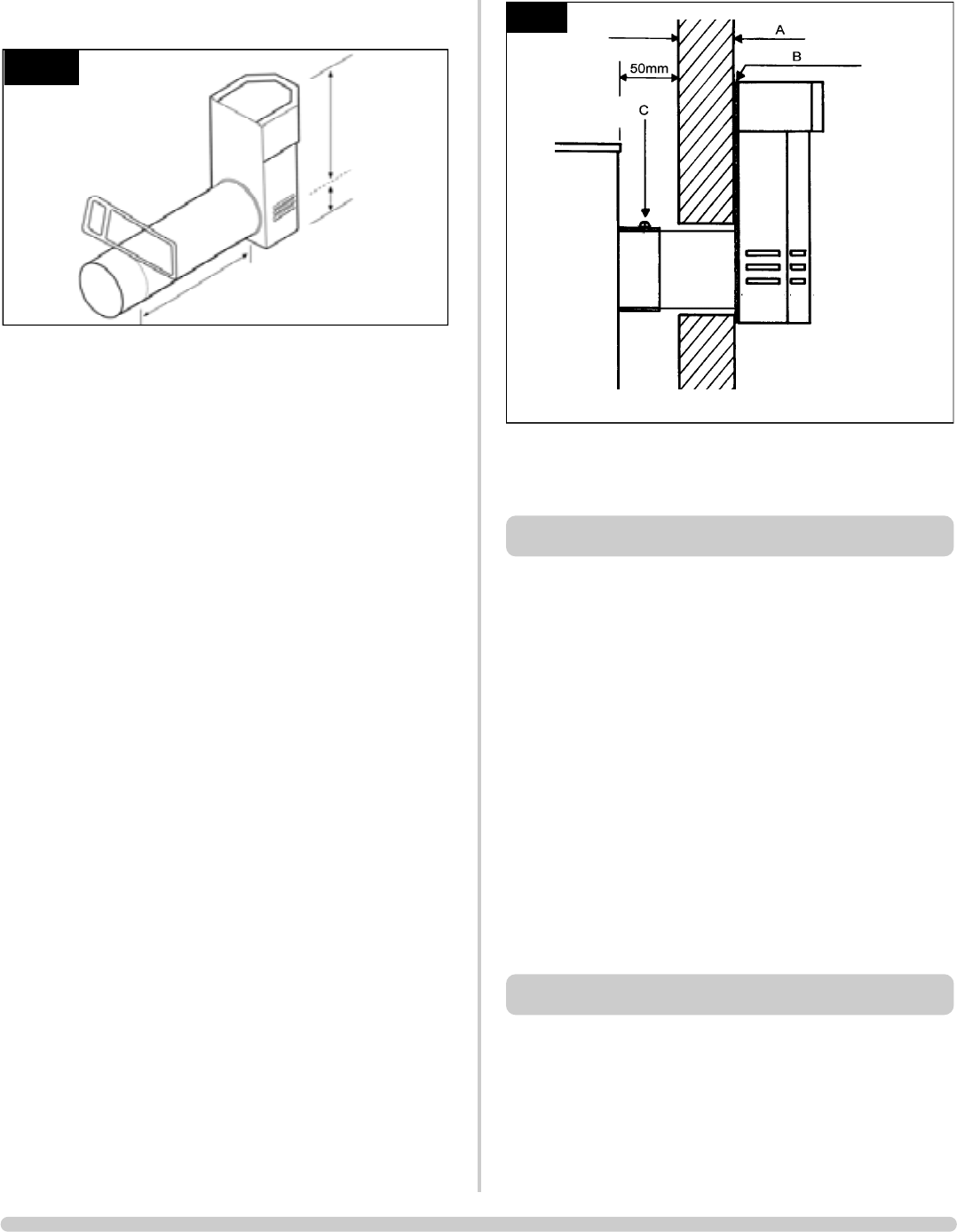
3.7 From outside:
• Apply a bead of suitable weatherproof sealand (silicone
or similar) around the perimeter of the back of the terminal,
see ‘B’, Diagram 3
• Feed the flue through the wall ensuring it travels
smoothly
3.8 From inside:
• Engage the inner flue in the inner spigot and the outer
flue in the outer spigot
• Ensure the rubber seals on the spigots are intact
3.9 From outside:
• Insert four screws in the flanges of the flue terminal
• Make sure the sealant has formed a water tight joint to
the wall
3.10 From Inside
• Secure the flue to the spigot by drilling a 3.5 mm hole
through the larger hole in the spigot and insert the stainless
steeel screw supplied, see ‘C’ Diagram 3
AR0630a
2
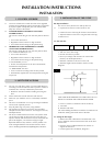
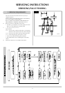
200mm min
600mm max
Any terminal less than 2 metres above any access (at ground
level, balcony or above a flat roof where people have
access) must be fitted with the guard supplied, Diagram 4.
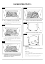
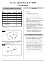
There are two types of exit flue terminal: horizontal and
vertical.
For horizontal:
• Decide on the terminal position
• Measure the height from the top of the fire to the centre
of the required hole
For minimum and maximum dimensions, see Diagram 3.
To fit the flue you must have access to the top or the side of
the fire to connect the flue. When a horizontal terminal is
used:
• Assemble the vertical sections
• Add the 90° elbow
• Add the horizontal section and terminal – only the
horizontal part can be reduced in size
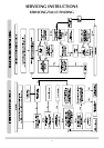
A masonry installation requires the addition of a suitable
lintel to support the opening. Refer to Balanced Flue
Technical Information for details of the flue length.
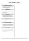
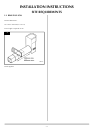
This flue rises vertically from the top of the fire, then
continues horizontally outward. Diagram 3.
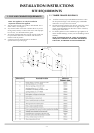
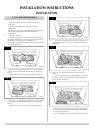
The basic kit comprises:
1 x 500mm vertical length
1 x 500mm terminal length
1 x 90 degree elbow
5. TOP FLUE UP AND OUT KIT
4. TOP EXIT
3
AR0606