


TAPI Model 265A Chemiluminescence Ozone Analyzer
Manual Addendum, Rev. B, DCN 5254
2
PRINTED DOCUMENTS ARE UNCONTROLLED
1.2 Electrical and Pneumatic Connections
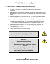
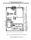
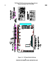
1. See Figure 1-2 and Figure 1-3 to locate the rear panel electrical and pneumatic
connections.
2. Attach the pump to the “Exhaust Out” port on the instrument rear panel. The exhaust from
the pump should be vented to atmospheric pressure and out of the room, because of its NO
content.
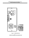
3. Attach the sample inlet line to the sample inlet port. The pressure of the sample gas at the
inlet port should be at ambient pressure and constant. See Figure 1-3.
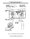
4. Attach a cylinder with 10,000 ppm ±10% of nitric oxide (NO) in nitrogen (N
2
), with an
appropriate pressure regulator, to the 1/8” SS port on the rear panel as shown in Figure
1-2. The cylinder’s pressure regulator should be set to deliver gas at 20 PSIG ±10%.
5. Attach the analog output connections to a strip chart recorder and/or data-logger. See
Figure 1-2 for connector pin-out definitions. See Figure 1-4 for V/F board switch settings.
Factory default setting is 0-5 VDC.
6. Connect the power cord to the correct line voltage.
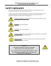
WARNING
Analyzer Exhaust Contains Nitric Oxide Gas.
Vent pump exhaust to a well-ventilated area at atmospheric
pressure.
WARNING
Lethal voltages present inside case.
Do not operate with cover off during normal operation.
Before operation, check for correct input voltage and
frequency.
Do not operate without proper chassis grounding.
Do not defeat the ground wire on power plug.
Turn off analyzer power before disconnecting
electrical subassemblies.