51
ENGLISH
EN
GENERAL
This symbol indicates WARNING.
Personal injury and/or damage to
property may result if the instructions
are not followed carefully.
You must read these instructions for use
and the accompanying pamphlet
“SAFETY INSTRUCTIONS”
carefully, before starting up the
machine.
SYMBOLS
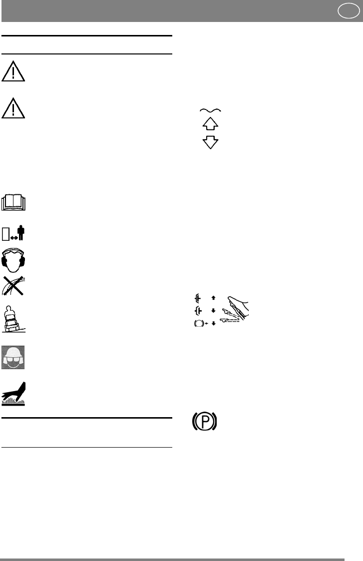
The following symbols appear on the machine.
They are there to remind you of the care and
attention required in use.
This is what the symbols mean:
Warning!
Read the instruction manual and the safety
manual before using the machine.
Warning!
Watch out for discarded objects. Keep
onlookers away.
Warning!
Always wear hearing protectors.
Warning!
This machine is not designed to be driven
on public roads.
Warning!
The machine, equipped with original
accessories, must not be driven in any
direction on slopes with a gradient greater
than 10º.
Warning!
Risk of crushing injuries. Keep hands and
feet well away from the articulated
steering joint.
Warning!
Risk of burn injuries. Do not touch the
silencer/catalytic converter.
CONTROLS AND
INSTRUMENTS
Items 1 - 19, see figures 1 - 7.
1. IMPLEMENT LIFTER
(President - Comfort - Royal - Pro16)
A pedal for raising front-mounted implement to
the transport position.
To lift up the implement, press the pedal down as
far as it will go. Then release the pedal, the
implement lifter is now locked in the raised
position.
To lower the implement, press the pedal down so
that the lock is released. Lower the implement
lifter to the working position by slowly lifting your
foot from the pedal.
2. HYDRAULIC LIFTER (Pro20)
Hydraulic implement lifter for raising front-
mounted implements to the transport position.
To raise the implement, press the rear
part of the switch. Release the switch
in the required position.
To lower the accessory, press the
front part of the switch. The switch
stays in the pressed position and the
implement lifter is lowered until it
reaches a floating position. This
means that the implement can follow
the contours of the ground.
The floating position, with the switch in the tilted
forward position, is recommended for normal use.
To secure the implement lifter, place the switch in
neutral.
NOTE! The hydraulic implement lifter must be
in floating position in order for the power take-
off to be connected.
3. SERVICE BRAKE
A pedal that acts on the machine’s braking system.
There are 3 positions:
1. Pedal released – service brake
not activated.
2. Pedal depressed halfway –
forward drive disengaged.
Service brake not activated.
3. Pedal fully depressed –
forward drive disengaged.
Service brake fully activated.
4. PARKING BRAKE
An inhibitor that can lock the brake pedal in the
depressed position.
Depress the brake pedal fully. Move the
inhibitor to the right and then release the
brake pedal.
The parking brake is released by pressing the brake
pedal. The spring-loaded inhibitor slides to one
side.
Make sure that the parking brake is released when
operating the machine.


