


3–Pump 33-Station Controllers Chapter 3: Installation 13 of 51
Chapter 3: Installation
3-1 Uncrating
3-Pump, 33-Station Controllers are shipped mounted on a skid, enclosed in a plastic
wrapper, and contained in a cardboard box.
1. Pry the crating away from the skid.
Note: Remove the nails holding the box to the skid and lift the box off
carefully; avoiding staples in the 1’ x 4’ wood supports. Cut the steel
banding.
2. Use a pry bar to remove the blocks securing the unit to the skid.
3. Lift unit from sides, inserting forklift under the base. The forks must be equidistant
from the centerline of the unit and the unit must be balanced on the forks. Lift
slowly and only high enough to clear the skid. Use a pry bar if necessary to
carefully remove the skid from the unit.
4. Lower slowly.
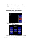
3-2 Mounting the Control Panel
Note: Before you mount the panel, consider how you run wiring to the vacuum
hoppers, the filter chamber atmospheric valve (if so equipped) and the pump
motor starter(s), vacuum switch(es), and vent valve(s).
Mount the panel on a flat, vertical area. It should be a visible area that gives your
operator access to the control. The panel requires a low voltage power drop as listed on
the serial tag.
3-3 Electrical Connections
Refer to local electrical codes, the schematic and connection diagrams supplied with this
unit and the serial tag for wiring considerations. Run all wiring in conduit if codes require
it.
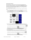
Making Control Panel Power Drop Wiring Connections
Hardwire the input power at 110/1/50-60 VAC or 230V/1/50-60 VAC, depending on the
specifications, which are located on the Control Panel Serial Tag. The main power
switch is located on the front of the enclosure.
Caution! We recommend that you protect PLC memory by providing the control
panel with a dedicated circuit, a true earth ground, and a spike/surge
protector.