


4
f) Re-assemble the quartz sleeve with spring in the UV chamber allowing the sleeve to protrude an equal
d
istance from both ends of the UV chamber.
g) Wet the o-rings and slide onto each end of the quartz sleeve and reassemble the gland nuts (hand tight is
sufficient).
h) Re-tighten all connections, turn on water and check for leaks.
I) Re-install the UV lamp and lamp connector as per prior instructions.
j
) Reconnect system to power source.
Note: If the system is put on a temporary by-pass or if it becomes contaminated after the disinfection system, it
w
ill be necessary to shock the system with household bleach for a full 20 minutes before resuming use of the
water.
C. UV SENSOR REPLACEMENT AND/OR CLEANING (Applies to S12Q-GOLD & S24Q-GOLD systems only):
1.
Mineral deposits and sediment may accumulate on the sensor probe decreasing the UV detection rate. Good
maintenance of filtration equipment will reduce the accumulation of residues. If necessary, remove the sensor
probe after a few months and proceed with cleaning process. Repeat the process as often as necessary to keep the
sensor probe clean.
2. Disconnect the UV sensor from the rear of the disinfection system and drain the reactor chamber as per prior
instructions. Remove the sensor probe by unscrewing retaining nut. Do not attempt to disassemble the sensor
probe itself. Any tampering with the internal components of the sensor probe will result in voiding the warranty.
The probe face should be cleaned with a commercially available scale remover (CLR, Lime-Away, etc.) and a lint
fr
ee cloth. Carefully reassemble the sensor probe into the sensor boss by first inserting the sensor o-ring and then
the sensor itself. Screw the sensor retaining nut and tighten to achieve a water tight seal. DO NOT OVER
TIGHTEN. Attach the sensor cable to the connector on the rear of the UV disinfection system.
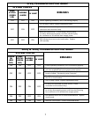
LAMP F
AILURE SYSTEM (Standar
d on S12Q, S24Q, S40Q)
The audible alarm and indicator lights on the systems continuously monitor the lamp operation. If the lamp does not
start at any time, the indicator light will not glow and the audible alarm will sound. This alarm indicates that the UV
lamp is no longer operating and must be corrected. Please refer to Troubleshooting Guide for corrective procedures.
ULTRAVIOLET MONITORING SYSTEM (Standard on GOLD models)
The ultraviolet sensor system features a complete warning system for continuous water protection by constantly sensing
the UV INTENSITY at the inside surface of the cell. The system features a single LED indicator light, which will show
three distinct colours, GREEN, YELLOW, and RED. When the UV output level changes, the warning system will operate
in the following manner:
GREEN indicates that the UV intensity is satisfactor
y and the unit is in good working order.
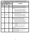
YELLOW indicates that the UV intensity is reduced, which could be due to any of the following factors :
• The lamp is losing str
ength and will soon need to be r
eplaced.
• The quartz sleeve and/or the sensor probe have become dirty. Mineral deposits or sediment in the
water that was not detected during the original water analysis may be the cause for this. The quartz
sleeve and sensor pr
obe should be cleaned and the system r
e-installed to deter
mine if dir
t was the
cause of the yellow light. If the LED light switches to yellow soon after the unit is installed or the
lamp has been replaced, dirt accumulation is most likely the cause.
• Inter
mittent voltage dr
op in the household power supply r
educing the lamp output. The lamp will
return to normal when the power is restored to full voltage. Note : The monitoring system will not
operate during power failures.
FLASHING RED indicates that system cut-of
f is imminent where solenoid is fitted. Immediate action is required.
RED indicates that the unit needs immediate attention, the audible alar
m will automatically sound when the LED
monitor light switches to red. If the lamp has been in service for a year or more it should be replaced. The quartz
sleeve and/or sensor probe may require cleaning. The alarm will continue until the sensor detects adequate UV
intensity
. When a lamp is r
eplaced it is recommended to clean the quartz sleeve and sensor probe prior to returning
the system to service.
SOLENOID CONT
ACTS (Standar
d on S12Q-GOLD & S24Q-GOLD models)
GOLD units come equipped with the capability of adding an optional solenoid valve available from your dealer. This
nor
mally closed solenoid will work in conjunction with the UV monitoring system physically stopping the water flow if
the UV sensor determines that the water is not being adequately treated. The LED indicator will be red and the audible
alarm will be sounding. Water will only be allowed to flow when the UV disinfection system senses that the quality of
the water has returned to a safe state. Ideally, the solenoid valve should be installed on the influent side of the
disinfection system. To install, disconnect power supply prior to opening disinfection system cover. Plumb solenoid valve
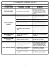
WARNING SYSTEMS: