


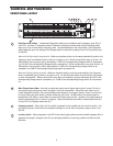
5 CUT ONLY switch - When pressed in, the LED switch lights and all the Equalizer sliders serve to attenuate
their frequency areas only (there is no boost) by up to 6 or 12 dB, depending upon the setting of the
RANGE switch (see #7 below). The Cut Only switch should be used when you need to notch out certain
frequencies in order to reduce feedback or “ring out” a room. See the “Using the S curve 231 to remove
feedback” section in this manual (page 14) for more information.
6 LEVEL METER - This eight segment LED bar VU meter displays the Input Level from –30dB to +18dB.
7 Range switch - When pressed in, the LED in the switch lights and the Equalizer sliders cut or boost each
frequency area by up to 6 dB, allowing fine frequency curves to be set. When out (in the up position), the
Equalizer sliders cut or boost each frequency area by up to 12 dB, allowing coarse control. The setting of
the switch also affects how Cut Only operates—see #1 on the previous page for more information.
8 Equalizer switch - When not pressed in, the equalization circuitry is made inactive so that the signal
passes through unaffected, regardless of the settings of the Equalizer or Level sliders. When pressed in,
the LED in the switch and the sliders light green and the equalization circuitry affects the signal as per the
setting of the front panel Equalizer and Level sliders (see #1 and #2).
9 Power switch - Use this to turn the power on and off.
10 Channel 2 - Same functions and controls and Channel 1.
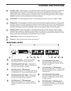
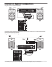
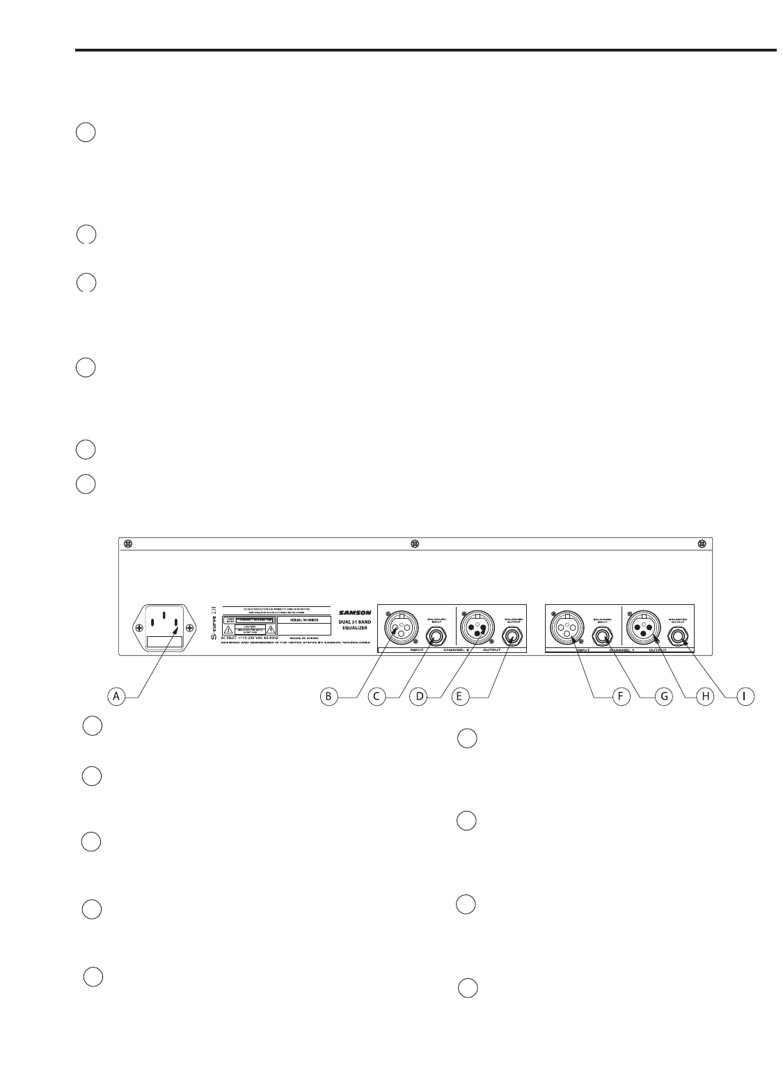
A AC input fuseholder - Connect the supplied
heavy gauge 3-pin “IEC” power cable here.
B CH2 Balanced XLR jack input - Electronically
balanced XLR jack input. Wiring is as follows: pin
2 hot, pin 3 cold, and pin 1 ground.
C CH2 Balanced 1/4" TRS jack input -
Electronically balanced 1/4" TRS jack input. Wiring
is as follows: tip hot, ring cold, and sleeve ground.
D CH2 Balanced XLR jack output - Electronically
balanced XLR jack output. Wiring is as follows:
pin 2 hot, pin 3 cold, and pin 1 ground.
E CH2 Balanced 1/4" TRS jack output -
Electronically balanced 1/4" TRS jack output.
Wiring is as follows: tip hot, ring cold, and sleeve
ground.
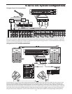
Controls and Functions
REAR PANEL LAYOUT
F CH1 Balanced XLR jack input -
Electronically balanced XLR jack input.
Wiring is as follows: pin 2 hot, pin 3 cold,
and pin 1 ground.
G CH1 Balanced 1/4" TRS jack input -
Electronically balanced 1/4" TRS jack input.
Wiring is as follows: tip hot, ring cold, and
sleeve ground.
H CH1 Balanced XLR jack output -
Electronically balanced XLR jack output.
Wiring is as follows: pin 2 hot, pin 3 cold,
and pin 1 ground.
I CH1 Balanced 1/4" TRS jack output -
Electronically balanced 1/4" TRS jack out-
put. Wiring is as follows: tip hot, ring cold,
and sleeve ground.