


4
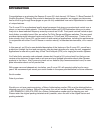
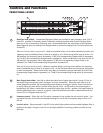
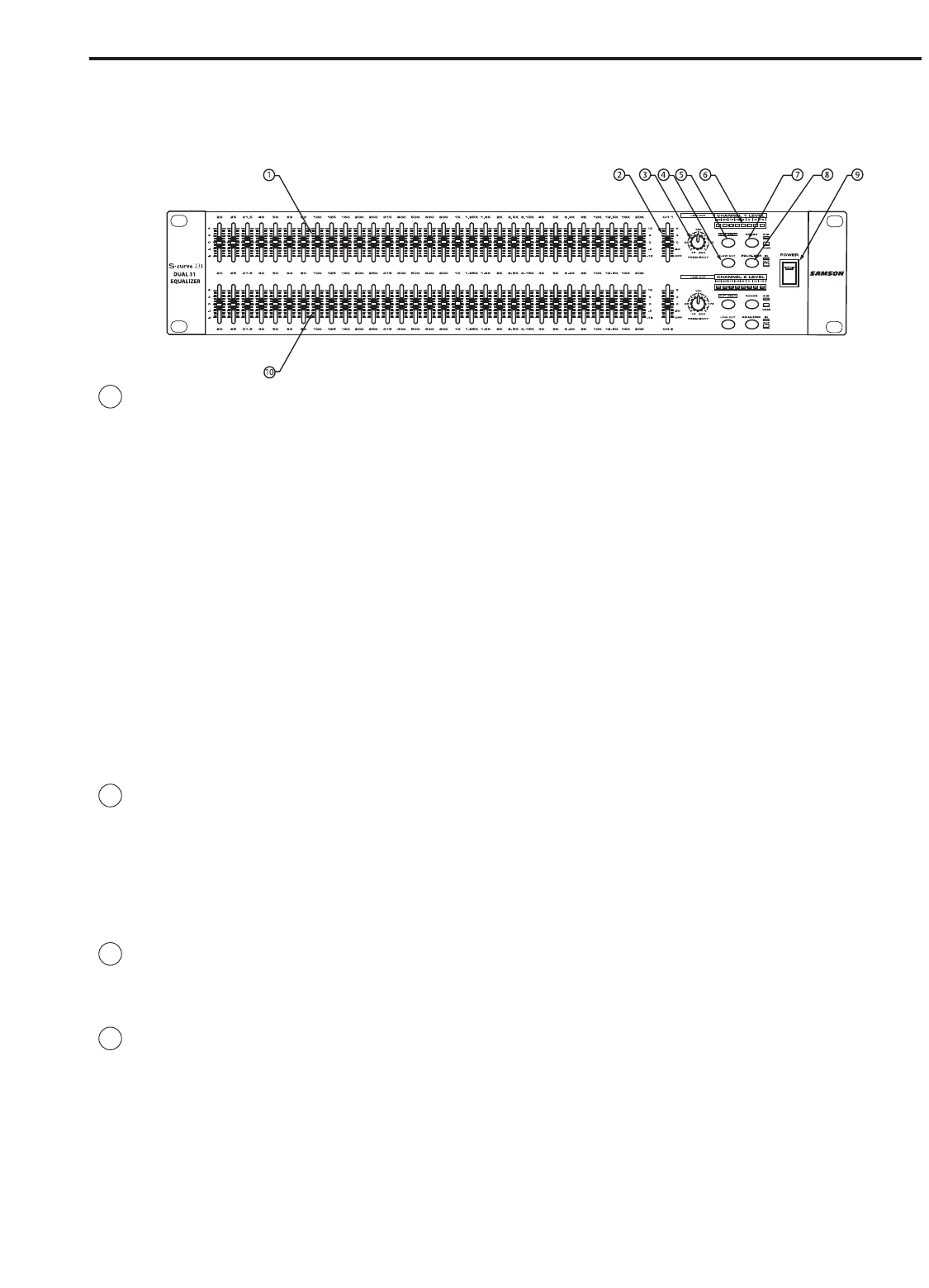
1 Equalizer level sliders - Independent Equalizer sliders are provided for each frequency area (The S
curve 231 provides 31 frequency areas).Calibration markings on either side of each Equalizer slider
allow you to cut or boost each frequency area. As described below, the exact action of the Equalizer
sliders depends upon the setting of the Range switch as well as the setting of the Cut Only switch (see
#3 and #5).
When the Cut Only switch is not pressed in: When an equalizer slider is at its center detented 0 position, the
frequency area is unaffected (that is, there is no boost or cut). When moved all the way up (to the +12
dB) position, the frequency area is boosted by 12 dB (if the corresponding Range switch is notpressed
in) or 6 dB (if the corresponding Range switch is pressed in). When moved all the way down (to the -12
dB position), the frequency area is attenuated by 12 dB (if the corresponding Range switch is not
pressed in) or 6 dB (if the corresponding Range switch is pressed in).
When the Cut Only switch is pressed in: When an equalizer slider is at its top-most position, the frequency
area is unaffected (that is, there is no boost or cut). As the Equalizer slider is moved down, the frequen-
cy area is attenuated. When moved all the way down, the frequency area is attenuated by 6 dB (if the
corresponding Range switch is pressed in) or 12 dB (if the corresponding Range switch is not pressed
in).
2 Main Output level slider - Use this to adjust the output level of signal leaving the S curve 231 via its
rear-panel output connectors (see D on page 5 for more information). When the main slider is at its
center detented 0 position, the corresponding output signal is at unity gain (that is, there is no level cut
or boost). When the main slider is moved all the way up (to the +6 dB) position, the output signal is
boosted by 6 dB. When a Level slider is moved all the way down (to the ∞ position), the output signal is
infinitely attenuated (that is, there is no signal). Note that the Main level slider is deactivated when the
S curve 231 is in Bypass mode (see #7).
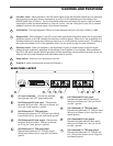
3 Frequency control - When the Low Cut switch is pressed in, the variable low cut control is active. You
can adjust the point at which the low frequencies begin to roll off with a frequency range of from 15 to
200 Hz.
4 Low Cut switch - When pressed in, the LED in the switch lights yellow and the variable highpass filter is
applied to the signal. Using the Low Cut can be highly effective in removing rumble and other low fre-
quencies.
Controls and Functions
FRONT PANEL LAYOUT