


13
MXP144/MXP144FX
ENGLISH
FRANÇAISDEUTSCHEESPAÑOLITALIANO
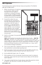
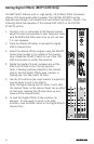
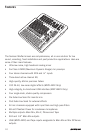
Stereo Input Channel Section
The following section details four stereo input channels.
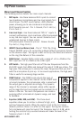
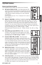
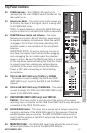
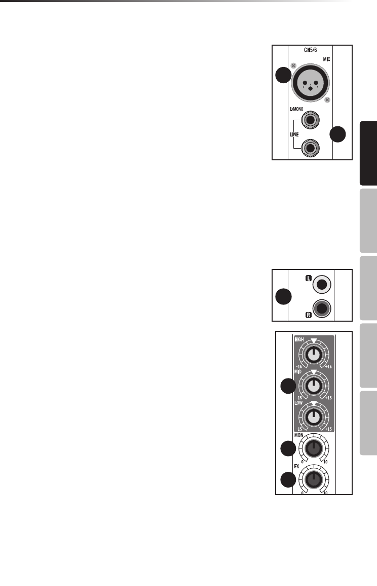
14. MIC Inputs (CH5/6 & CH7/8) - Use these balanced XLR
inputs to connect low Impedance microphones and low
level signals from direct boxes. The MIC inputs feature
+48V phantom power, allowing you to use condenser
microphones.
XLR Connector pin-out - Pin 1: Ground, Pin 2: Hot (+),
Pin 3: Cold (-)
15. Stereo ¼” Input Jacks - Use the ¼” jacks for connecting
stereo line level sources. For stereo inputs use the LINE L to connect
the left channel and the LINE R to connect the right channel. Use the
LEFT input when connecting a mono input signal to the Stereo Input
channels. You can connect outputs from high impedance microphones,
synthesizers and drum machines to these inputs. The LINE inputs have a
nominal operating level of -40dBV through - 10dBV.
TRS phone jacks Connector pin-out - Sleeve: Ground, Tip: Hot (+), Ring:
Cold (-)
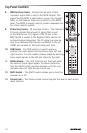
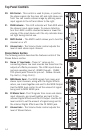
16. Stereo RCA Input Jacks (CH9/10 & 11/12) - The stereo
channel’s RCA connectors accept signals from stereo
line devices. The RCA line level inputs have a nominal
operating level of -40dBV through - 10dBV.
17. Equalizer (HIGH, MID, and LOW) - This three-band
equalizer allows you to contour a channel’s high, mid,
and low frequency bands. When the control is set to the
12 o’clock (detent) position, there is no effect on the
signal. Turning the controls fully clockwise will raise the
level of the frequency band +15 dB, while turning the
controls fully counterclockwise will lower the level of
the frequency band -15 dB.
18. MON Auxiliary Control - Controls the amount of that
channel’s signal that is sent to the MON Output. The
signal feeding MON is sent before, or pre, the channel
fader, so the channel fader has no effect on the MON
level. The MON is usually used to create a separate mix
for a floor monitor system.
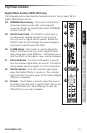
19. FX Auxiliary Control - The channel’s FX knob controls the amount of signal
that is sent to the effects bus. The signal of the FX bus in the MXP144FX
is routed to the Digital Effects section for on-board signal processing. The
FX signal can also be sent to an external effect device connected to the
FX SEND jack located on the front panel jack field.
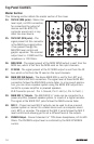
Top Panel Controls
14
15
16
17
18
19
20
22
23
21
16
17
18
19
20
22
23
21