


7
En
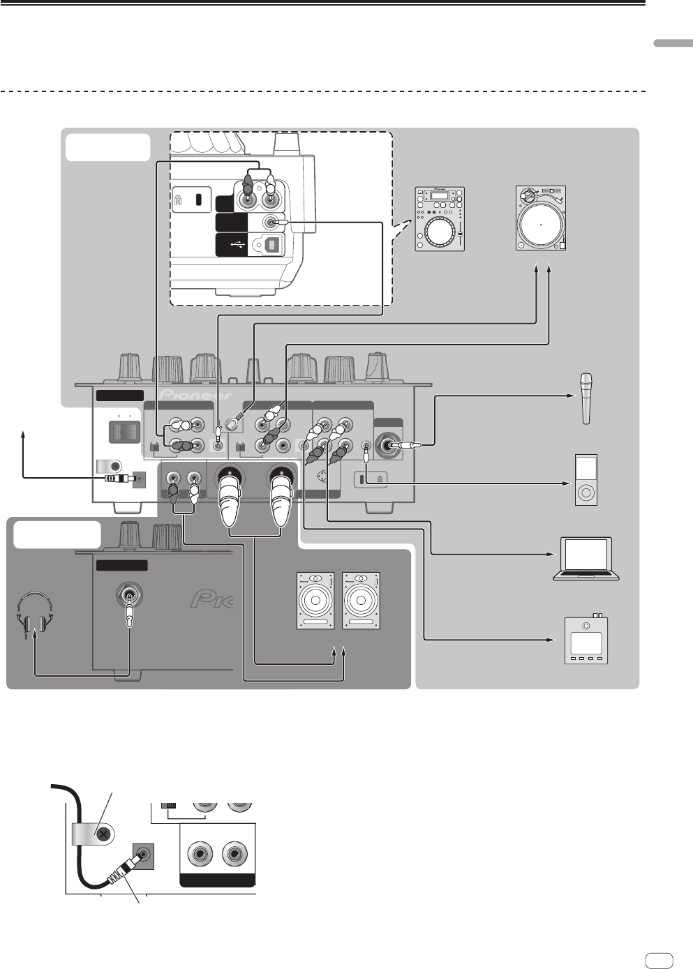
Connections
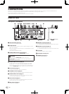
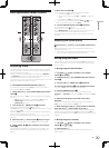
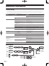
Connecting the input/output terminals
! When creating a DVS (Digital Vinyl System) combining a computer, audio interface, etc., be careful in connecting the audio interface to this unit’s
input terminals and in the settings of the input selector switches.
Also refer to the operating instructions of the DJ software and audio interface.
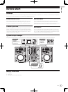
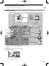
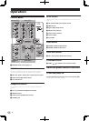
Rear panel, front panel
Audio output
section
Audio input
section
ON
DC IN
L
L
LINE PHONO
PHONO / LINE CD
CONTROL
SIGNAL
GND
RL
3 COLD
2 HOT
1GND
R
R
L
PHONO / LINE CD
CONTROL
R
L
R
1
23
OFF
CH-1 AUX
MASTER 1MASTER 2
MIC
LINE PHONO
CH-2
AUDIO
OUT
RL
CONTROL
USB
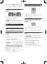
To power outlet
Audio cable
Audio cable
Audio cable
Audio cable
Audio cable
Audio cable
Audio cable
To ground wire
terminals
Microphone
Microphone cable
To microphone
Analog playerDJ player
AC adapter
(included)
R
L
To audio output
terminals
Portable audio
device
To audio output
terminals
To audio output
terminals
To audio output
terminals
To audio input terminals
Powered speaker, component,
amplifier, etc.
R R
R
L
R
L
Ground wire
R
L
Computer
Control cord
1
synthesizer
INPUT
1
2
3
4
EQ
POWER
INPUT
1
2
3
4
EQ
POWER
Example:
CDJ-350
LL
Headphones
cord
Headphones
Rear panel
Front panel
1 To use the fader start function, connect a control cord (page 12).
The fader start function can only be used when connected to a Pioneer DJ player.
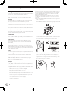
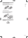
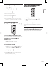
Cord hook
Loosen the cord hook’s screw and pinch the AC adapters’
power cord under the hook.
DC IN
LR
R
MASTER 2
AC adapter’ s power cord
Cord hook
! Place the cord hook out of reach of children. If a child should
swallow it, contact a physician immediately.