


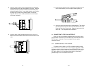
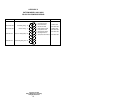
4.2.2 CONNECTION TO A “DCE” DEVICE
Since the Model 1030 is wired as a DCE, you cannot connect it
directly to another DCE such as a modem, multiplexer or printer. If you
need to connect the Model 1030 to another DCE device, you must use
a
null modem cable
wired according to diagram below. We recommend
that you use the shortest possible cable, preferably 6 feet or less.
Connection to Model 1030
†
Connection to DCE Device
DB-25 Pin No. DB-25 Pin No.
1....................................................1
2....................................................3
3....................................................2
4....................................................8
8....................................................4
6..................................................20
20....................................................6
17..................................................24
24..................................................17
7....................................................7
†
Note: When connecting to another DCE device, the Model 1030
should be configured for “external clock” (see Section 3.2).
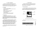
4.3 OPERATING THE MODEL 1030
Once the Model 1030 is properly configured and installed, it should
operate transparently—as if it were a standard cable connection.
Operating power is derived from the RS-232 data and control signals;
there is no “ON/OFF” switch. All data signals from the RS-232 interface
are passed straight through. In addition, one hardware control signal is
passed in either direction.
APPENDIX A
PATTON MODEL 1030/1030S SPECIFICATIONS
Transmission Format: Synchronous, full or half duplex
Transmission Line: Two unconditioned twisted pair 19 - 26
AWG
Clocking: Internal, external or receive loopback
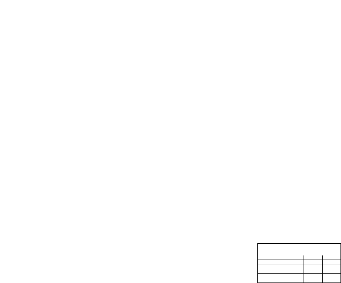
Range: (See table below)
Interfaces: EIA RS-232, CCITT V.24
Data Rates: 1200 - 19.2 Kbps
Isolation: Minimum 1500 V RMS via custom
transformers
Surge Protection: 600W Surge Protection (10x1000µs
waveform) (Model 1030S only)
Control Signals: CTS turns on 8 or 53 mS (switch selectable)
after the terminal raises RTS; carrier
continuous or controlled by RTS; DCD turns
on immediately after recognizing the
received signal from the line
Connectors: DB-25 male or female on RS-232 side; RJ-
11, RJ-45 or terminal block with strain relief
on line side
Power Supply: No external power required, uses power
from EIA data and control signals
Temperature Range: 0-60°C (32-140°F)
Altitude: 0-15,000 feet
Humidity: 5 to 95% noncondensing
Dimensions: 2.66” x 2.10” x 0.73”
Weight: 2 oz.
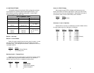
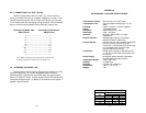
13 14
Data
Rate
Wire Gauge
19 24 26
19,200 7.5 3.5 2.5
9,600 10.0 3.5 2.5
4,800 10.0 7.0 4.0
2,400 10.0 8.5 5.0
1,200 11.0 8.5 6.0
Model 1030 Distance Table (miles)