


2.0 GENERAL INFORMATION
Thank you for your purchase of this Patton Electronics product.
This product has been thoroughly inspected and tested and is
warranted for One Year parts and labor. If any questions or problems
arise during installation or use of this product, please do not hesitate to
contact Patton Electronics Technical Support at (301) 975-1007.
2.1 FEATURES
• Point-to-point or multipoint operation
• Internal, external or receive loopback clocks (switch selected)
• Data rates to 19,200 bps
• Range to 11 miles
• Carrier “on” or “controlled” (switch selected)
• Options for easy daisy chain installation
• Full or half duplex operation
• Transformer isolated
• Custom VLSI chip filters each data rate separately
• Built-in Silicon Avalanche Diode surge protection
2.2 DESCRIPTION
The Patton Electronics Model 1030 synchronous, multipoint
short range modem provides exceptional versatility in a compact
package. Measuring only 2.66” x 2.10” x and 0.73”, the Model 1030 is
suitable for many applications where connection space is limited. The
Model 1030 supports up to twelve drops, and requires no AC power or
batteries for operation.
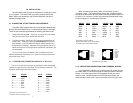
Operating at switch selectable data rates between 1.2 and 19.2
Kbps, the Model 1030 can attain distances between 3.5 and 8.5 miles
over two 24 AWG twisted pair (thicker gauges may yield better
distances). The Model 1030 operates half duplex or full duplex, and
accommodates three clocking methods: internal, external and received
loopback. Transformer isolation guards the Model 1030 against
ground looping in building-to-building applications. Other features
include a selectable RTS/CTS delay of 7 mSec or 53 mSec, and
selectable carrier status of constantly on or RTS controlled.
The Model 1030S is a surge protected version of the Model 1030
that uses Silicon Avalanche Diodes to provide 600 watts of transient
protection per wire.
3
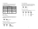
3.0 CONFIGURATION
The Model 1030 provides seven configuration switches, which
allow selection of carrier control method, clocking method, RTS/CTS
delay and data rate. This section describes switch locations and
explains all possible switch configurations.
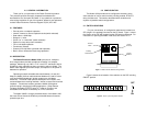
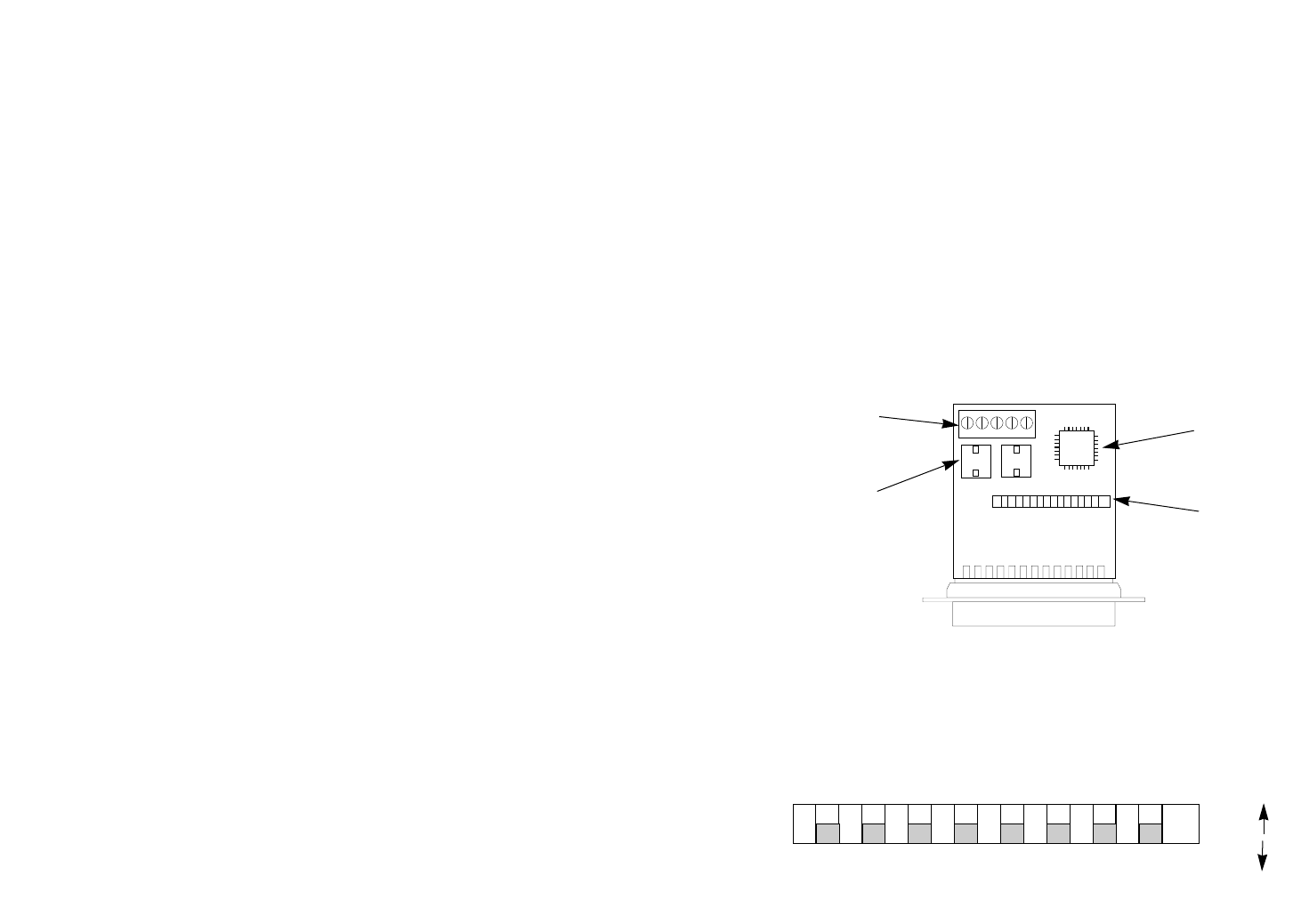
3.1 SWITCH LOCATIONS
For your convenience, all configuration switches are located on a
SIP (single in-line package) mounted on the PC board. Figure 1 shows
the location of the SIP with respect to other PC board components. For
instructions on opening the Model 1030 case, see Section 4.1.2.
Figure 2 shows the orientation of the switches on the SIP, including
ON/OFF position.
4
1 2345678
ON
OFF
Figure 1. Model 1030 PC board showing switches
Figure 2. Close up of configuration switches
PATTON
PE068
XXXX
Control
Switches
Terminal
Block
Patton
VLSI chip
Isolating
Transformers