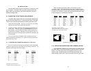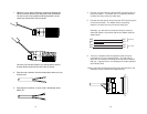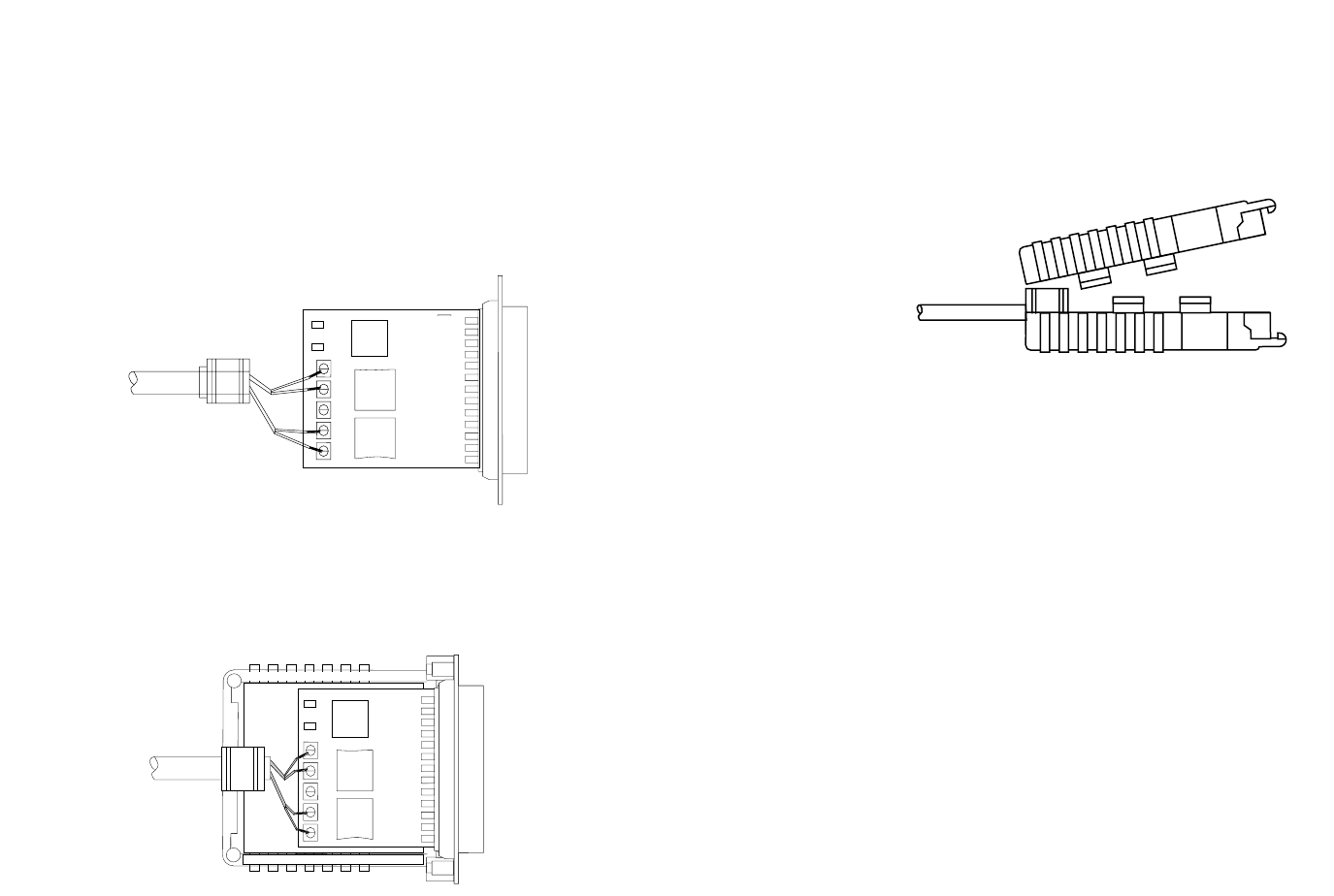
8. Place the 2 halves of the strain relief assembly on either side
of the telephone wire and press together very lightly. Slide the
assembly so that it is about 2 inches from the terminal posts
and press together firmly. If your cable diameter is too small or
too large for our strain relief, please contact our technical
support. We have strain relief assemblies to accommodate
most cable diameters.
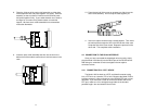
9. Insert the strain relief assembly and wire into the slot in the
bottom half of the modem case and set it into the recess in the
case.
RCV G XMT
RCV G XMT
10. Place the top half of the case as necessary to slide it over the
strain relief assembly. Do not snap the case together yet.
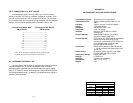
11. Insert one captive screw through a saddle washer. Then insert
the entire piece through the hole in the DB-25 end of the case.
Snap that side of the case closed. Repeat the process for the
other side. This completes cable installation.
4.2 CONNECTION TO THE RS-232 INTERFACE
Once you have connected the twisted pair wires correctly, simply
plug the Model 1030 directly into the DB-25 port of the RS-232 device.
After doing so, remember to insert and tighten the two captive
connector screws.
4.2.1 CONNECTION TO A “DTE” DEVICE
The Model 1030 is wired as a DCE, and therefore wants to plug
into a DTE such as a terminal, PC or host. Because the Model 1030 is
interface powered, a direct connection to the RS-232 DTE port is most
desirable. If you must use a cable to connect the Model 1030 to the
DTE port, make sure it is a
straight through
cable of the shortest
possible length—we recommend 6 feet or less.
11 12


