


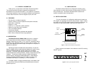
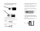
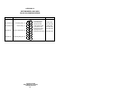
1. Open the unit by gently inserting a screwdriver between the
DB-25 connector and the lip of the plastic case (see below).
You don’t have to worry about breaking the plastic, but be
careful not to bend the D-sub connector.
Once the unit has been opened, you will be able to see the
terminal blocks located at the rear of the PC board.
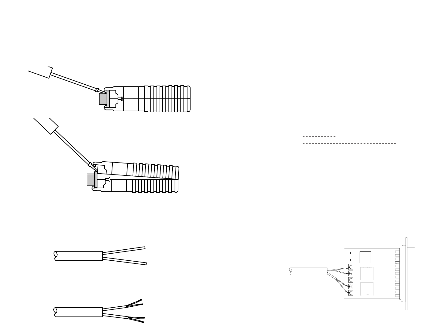
2. Strip the outer insulation from the twisted pairs about one inch
from the end.
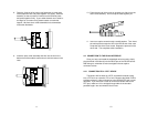
3. Strip back the insulation on each of the 2 twisted pair wires
about .25”.
4. Connect
one pair
of wires to the two XMT (transmit) poles on
the terminal block. The Model 1030 is not polarity sensitive,
so either wire may connect to either pole.
5. Connect the
other pair
of wires to the two RCV (receive) poles
on the terminal block. The Model 1030 is not polarity
sensitive, so either wire may connect to either pole.
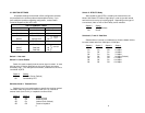
Ultimately, you will want to construct a two pair crossover
cable that makes a connection with the two Model 1030s as
shown below:
6. If there is a shield around the telephone cable it may be
connected to “G” on the terminal block. To avoid ground
loops, we recommend connecting the shield at the computer
end only. A ground wire is
not necessary
for proper operation
of the Model 1030.
7. When you finish connecting the wires to the terminal block, the
assembly should resemble the diagram below:
RCV G XMT
9 10
XMT RCV
XMT RCV
GG
RCV XMT
RCV XMT
To Shield (Optional)
}
One Pair
}
One Pair