


PAGE 14 — B-SERIES TROWEL — PARTS & OPERATION MANUAL — REV. #1 (12/03/01)
B-SERIES TROWEL — INSTRUCTIONS
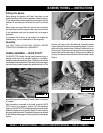
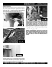
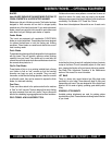
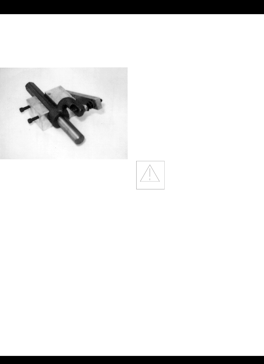
The easiest way to make this adjustment is to use the Trowel Arm
Adjustment Fixture, Part Number 1817 (pictured below). This
fixture will allow consistent adjustment of the trowel arm fingers.
It comes with all the hardware necessary to properly accomplish
this maintenance and instructions on how to properly utilize this
tool. Adjusting the trowel arm fingers without a fixture requires a
special talent.
If a trowel arm adjustment fixture is not available and immediate
adjustment is necessary , we suggest the following procedure. If
you can see or feel which blade is pulling harder, adjust the bolt
that corresponds to that blade. Another way to determine which
blades need adjusting is to place the machine on a flat surface and
pitch the blades as flat as possible. Now, look at the adjustment
bolts. They should all barely make contact with the lower wear
plate on the spider. If you can see that one os them is not making
contact, some adjustment will be necessary.
It is possible to either adjust the “high” bolts down to the level of
the one that is not touching, or adjust the “low” bolt up to the level
of the higher ones. Verify that after adjustment, the blades will pitch
correctly. Often times, if the blades are incorrectly adjusted, they
will not be able to pitch flat. This is due to the adjusting bolts being
raised too high. Conversely, some times the adjusting bolts are too
low and the blades cannot be pitched enough.
Changing a Blade
It is recommended that all the blades be changed at the same time.
The machine may wobble or bounce if only some of the blades
are changed at one time.
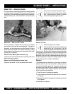
1. Place the machine on a flat, level surface. Adjust the blade pitch
control to make the blades as flat as possible. Note the blade
orientation on the trowel arm.
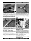
2. Remove the bolts and lock washers on the trowel arm, then
remove the blade.
3. Scrape all concrete particles from the trowel arm.
4. Install the new blade, maintaining the proper orientation for
direction of rotation.
5. Affix the bolts and lock washers.
6. Repeat steps 2-6 for all of the remaining blades.
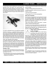
Hand Clutch Adjustment
Some finishers are equipped with a hand-operated clutch instead
of an automatic centrifugal clutch. Two types of hand clutches
have been installed. Both are belt-tightener type clutches. They
operate by removing slack in the V-belt which then transmits
power from the engine to the gearbox.
There are two reasons to adjust the hand clutch: 1) operator
comfort; 2) initial belt stretch and break-in.
The easiest and most simple adjustment is to adjust the clutch
cable housing using the adjusting nut located on the clutch lever.
Rotating the nut provides either more or less (depending upon the
direction of rotation) clutch engagement.
Always check to verify that the clutch will
properly disengage!
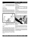
For operator comfort: start the trowel following
the instruction given earlier in this manual. Move
the throttle lever so that the engine is running
about 1/4 to 1/3 of full speed. Grip the trowel handle firmly and
carefully engage the clutch by squeezing the clutch lever toward
the handle with your left hand. After the trowel is stabilized and you
feel comfortable with its operation, use your right hand to adjust
the housing adjustment nut. Rotating the nut so that it backs out
of the lever housing increases the engagement and also the
squeezing force required to keep it engaged. Too much squeezing
force may cause premature hand fatigue. Too little squeezing
force may cause belt slippage and premature belt wear. Each
operator should experiment with the adjustment to get the optimum
combination of squeeze force and belt grip.
After initial break-in (approximately 8 hours) the above procedure
should be repeated to attain optimum operator comfort and belt
wear.
After considerable belt wear, the adjustments mentioned above
may have a little or no effect on clutch engagement. If this is the
case, the belt should be replaced.