


PAGE 28 — AR13HA/AR13HAR ROLLER (S/N 110301 & UP) • OPERATION AND PARTS MANUAL — REV. #0 (06/22/11)
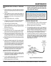
REMOVING AND REPLACING HYDROSTATIC
PUMP
1. Set the parking brake.
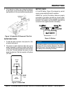
2. Disconnect the battery.
3. Clean the pump and all connections.
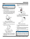
4. Mark and disconnect all hoses and lines from the pump.
5. Disconnect the forward / reverse control cable.
6. Disconnect the pump support bracket.
7. Remove the engine mounting bolts.
8. Elevate the pump and engine assembly using a proper
lifting device.
9. Disconnect and remove the hydrostatic pump assembly.
10. Repair or replace the hydrostatic pump as required.
11. Install the hydrostatic pump in the reverse order of
removal, using Locktite 271 on all mounting bolts and
nuts.
12. Test operation. Test and adjust the forward and reverse
relief pressures as required. Adjust the forward/reverse
control cable.
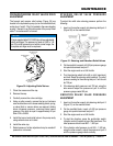
REMOVING AND REPLACING VIBRATION/
STEERING PUMP
1. Remove the hydrostatic pump as per preceding
instructions.
2. Remove all hoses and lines.
3. Disconnect the vibration / steering pump and remove.
4. Repair or replace pump as required.
5. Install the pump in the reverse order of removal, using
Locktite 271 on all mounting bolts and nuts.
6. Test operate. Test and adjust the forward and reverse
pressure relief valves as required. Adjust the forward/
reverse control cable. Test and adjust the vibration and
steering pressure relief valves as required.
MAINTENANCE
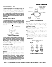
DRUMS AND MAIN FRAME
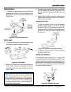
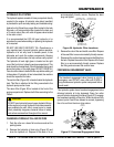
1. The front drum is designed to apply vibration and
compaction force to the operating surface for
compaction. This vibration and compaction force is
produced when the vibrator shaft is rotated. Maximum
efficiency is achieved only when the engine is operated
at full throttle.
2. A single drive motor is mounted on the left side of the
drum and is shock mounted. This type of drive motor
is designed for maximum torque and power.
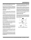
3. The vibrator is driven by a gear motor coupled to the
vibrator shaft. The vibrator assembly rotates inside of a
sealed housing containing oil to lubricate the bearings.
This side of the drum is also shock mounted.
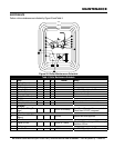
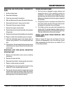
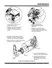
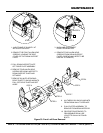
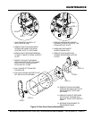
FRONT AND REAR DRUM REMOVAL AND
DISASSEMBLY.
Refer to Figure 32, Figure 33, and Figure 34 for the
removal and disassembly of the front and rear drums.
When reassembling the front drum, use Locktite 271 on
all mounting hardware.