


AR13HA/AR13HAR ROLLER (S/N 110301 & UP) • OPERATION AND PARTS MANUAL — REV. #0 (06/22/11) — PAGE 25
MAINTENANCE
Remember the freewheel engagement valve should only
be used in emergencies when the roller cannot be driven
due to engine or hydraulic system problems.
When towing of the roller has been completed, this
valve must be closed (turn allen wrench fully clockwise)
completely and the lock nut set. Failure to close this valve
completely will result in low power, improper speed, and
excessive hydraulic oil temperature.
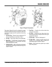
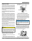
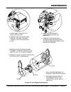
DRUM DRIVE
The drum drive circuit is a parallel, closed loop system
consisting of a hydrostatic pump, two relief valves, a
freewheel engagement valve, and front and rear drum
drive motors.
The hydrostatic pump is manually controlled by a cable
connected to the forward/reverse shift lever located on the
right side of the operator seat. When the shift lever is placed
in forward, high-pressure oil is supplied by the hydrostatic
pump to the valve block (port A). The valve block (manifold)
directs this high-pressure oil to the front and rear drum
drive motors. Return oil from the motors is returned to the
valve block (port B) and is returned to the suction side of
the hydrostatic pump.
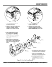
When shifted into reverse, the high-pressure and suction
ports on the hydrostatic pump are reversed. Oil flow is
then in the opposite direction of forward (port B becomes
high-pressure and port A becomes suction).
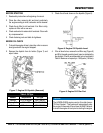
VIBRATION AND STEERING
The vibration and steering system is an open loop circuit
operated by a gear type pump. Separate relief valves control
each circuit. This system consist of the gear pump, relief
valves, electric vibration control valve, vibration drive motor,
steering valve, and steering cylinder.
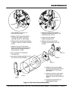
The vibration circuit is controlled by an electric control
valve located on the valve block (manifold). This valve is
controlled by the “ON/OFF” pushbutton switch mounted on
top of the travel lever.
High-pressure oil is supplied by the pump to the valve block
(port P) and is directed to the electric control valve. When
the pushbutton switch is in the “OFF” position, this valve is
open allowing oil to go to the steering valve, without driving
the vibration motor.
When the switch is in the “ON” position, the electric control
valve closes and oil is directed out of port 1 to the vibration
motor. Return oil from the motor returns to the valve block
via port 2 and is directed to the steering valve.
Steering is controlled by a steering valve and cylinder.
The steering wheel is direct coupled to the steering valve
controlling the oil flow to the cylinder. Oil supplied from the
vibration circuit is directed to port 3 which connects to port
P of the steering valve. When steering is not being used,
oil passes out of port T of the valve block and returns to
the hydraulic tank. When the steering wheel is operated,
the steering valve closes and oil is directed to ports L or R
to extend or retract the steering cylinder.
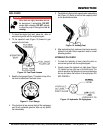
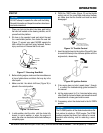
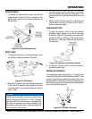
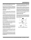
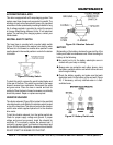
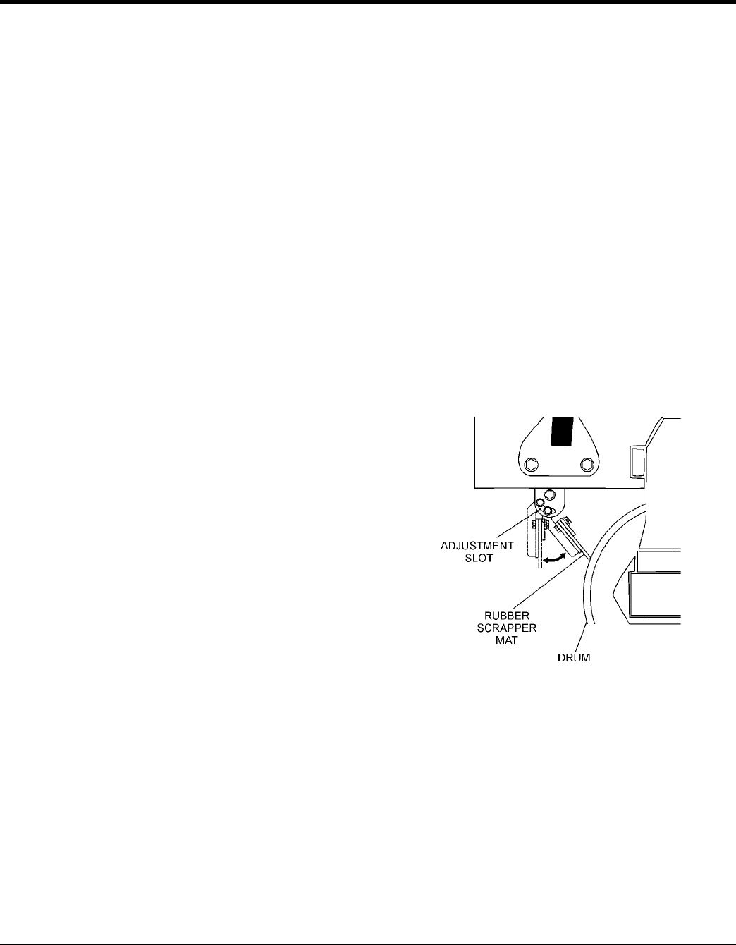
RUBBER SCRAPPER MAT
Rubber scraper mats have been provided for the cleaning
of the front and rear drums. Adjust the scrapers mats as
close as possible to the drums, using the slotted holes
(Figure 28) provided. Replace these rubber mats when
they become badly worn.
Figure 28. Scraper Bar Adjustment