


PAGE 24 — AR13HA/AR13HAR ROLLER (S/N 110301 & UP) • OPERATION AND PARTS MANUAL — REV. #0 (06/22/11)
HYDRAULIC OIL SYSTEM
The hydraulic system consists of a two-pump stack directly
coupled to the engine. A hydraulic valve block (manifold)
is provided for quick and easy testing and troubleshooting.
Hydraulic oil is filtered by a screen filter located in the tank
filler neck, a 40 micron suction filter located in the tank, and
a 10 micron return filter, with cold oil bypass valve located
in the return circuit.
It is recommended that ISO 46 type hydraulic oil or
equivalent be used when adding or replacing the hydraulic
oil is required.
DO NOT USE MULTI-VISCOSITY OIL. Cleanliness is a
very important part of proper hydraulic system operation.
Hydraulic oil is not only used to transfer power; it also
lubricates and cools the system components. Keeping
the hydraulic system clean can help reduce costly repairs.
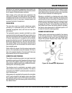
The hydraulic oil level sight glass is located on the right
rear of the front drum, below the engine compartment. This
level should be checked daily. Oil must be below the top and
above the bottom of the sight glass. DO NOT OVERFILL!
Care should be taken to clean the filler cap before adding oil
to the system. If hydraulic oil has to be added, the machine
should be inspected for leaks.
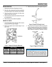
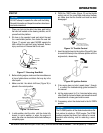
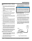
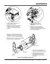
The suction filter (Figure 26) is located inside the hydraulic
tank. This filter is attached to the fitting connected to the
hydraulic pump suction hose.
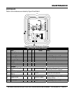
The return filter (Figure 26) is located at the front of the
engine compartment. Replace both filters according to the
Table 5.
CHANGING HYDRAULIC OIL AND FILTERS
1. Park the roller on a clean flat work area and set the
parking brake.
2. Remove the hydraulic oil drain plug (Figure 26) and
drain the hydraulic oil. Dispose of the used oil in an
CAUTION
DO NOT open hydraulic lines or loosen hydraulic fittings
while engine is running! Hydraulic fluid under pressure
can penetrate the skin, blind, cause burns or create
other potentially dangerous hazards follow all safety
instructions as described throughout this manual.
MAINTENANCE
environmentally friendly manner. Replace the drain
plug and tighten.
Figure 26. Hydraulic Filter Locations
3. Remove the return filter and install a new filter. Dispose
of the used filter in an environmentally friendly manner.
4. Disconnect the suction hose and remove the fitting from
the tank. Replace the suction filter. Dispose of the used
filter in an environmentally friendly manner. Replace
the fitting and reconnect the suction hose.
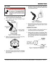
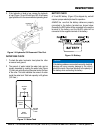
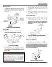
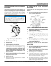
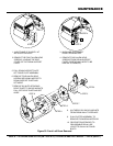
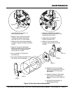
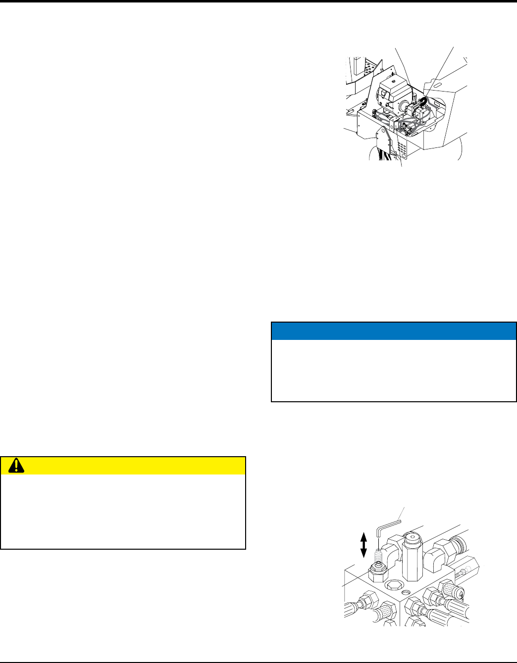
FREEWHEEL ENGAGEMENT VALVE
This hydraulic system has a freewheel engagement valve
allowing hydraulic oil to be bypassed. Open (turn allen
wrench counter-clockwise) this valve (Figure 27) to engage
the freewheel capability of the roller. When the valve is fully
opened, ports A and B are allowed to connect, bypassing
the oil to and from the drum drive motors.
Figure 27. Freewheel Engagement Valve
HYDRAULIC
OIL DRAIN
PLUG
HYDRAULIC OIL
RETURN FILTER
HYDRAULIC OIL
SUCTION FILTER
HYDRAULIC OIL
CAP/FILLER PORT
NOTICE
The freewheel engagement valve (towing) is only for
emergency use. DO NOT move roller over 2 MPH or
long distances as hydraulic system component failure
could result..
TOW
FREEWHEEL
ENGAGEMENT
VALVE
ALLEN
WRENCH
OPEN
CLOSED