


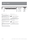
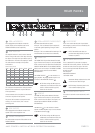
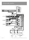
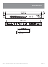
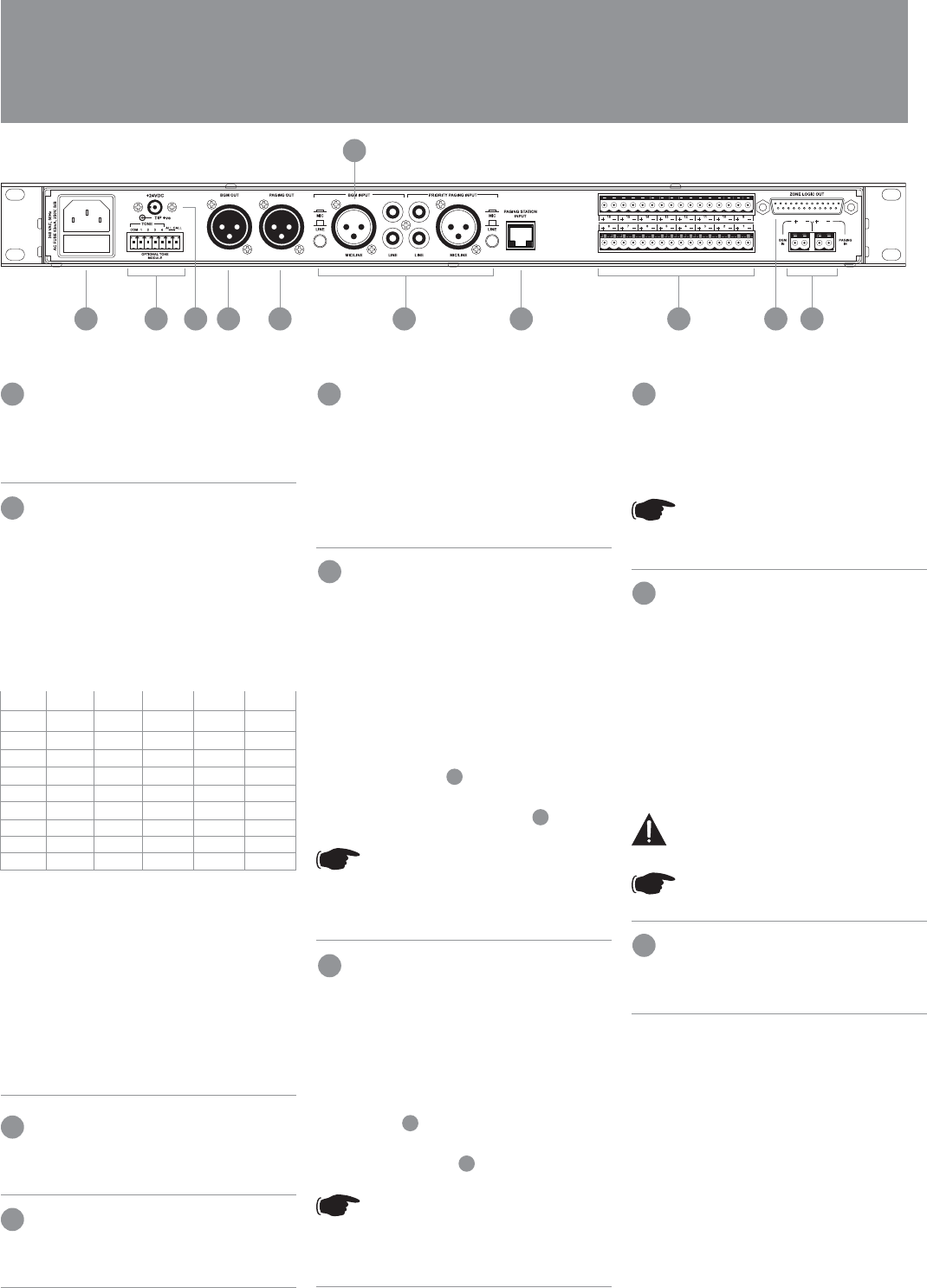
REAR PANEL
PAGE 5
AMIS ZONER16 INSTALLATION & OPERATION MANUAL
10
BGM and PAGING IN
These pluggable terminal blocks connect the
speaker outputs of the amplifi ers used for the
PAGING and BGM sources respectively.
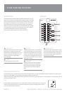
ZONE LOGIC OUT
This 25pin D-connector is used to control external
devices. They can be used to drive relays for attenu-
ator bypass. The outputs are open collector pull up,
24V 100mA drive. The total drive capacity is 150mA.
This table shows an example of the possible
combinations.
Number of relays per zone
Zone 1 Zone 2 Zone 3 Zone 4 Zone 5 Zone 6
4 2
4 1 1
3 3
3 2 1
3 1 1 1
2 2 2
2 2 1 1
2 1 1 1 1
1 1 1 1 1 1
This is based on the attenuators sold by Australian
Monitor. Other manufactures may have different
drive requirements.
If more attenuator drive is required use an external
drive box is required with more power.
The pins of the D-connector correspond to each
zone (e.g. Pin 3 is for Zone 3). Pins 17-25 are
common ground.
ZONE OUTPUTS
These pluggable terminal blocks connect to the
speaker runs for each respective zone.
PAGING STATION INPUT
This RJ45 socket accepts the CAT5 cable from the
PAGING STATION.
BGM and PRIORITY PAGING INPUTS
Both these channels have two inputs:
XLR input - This is a balanced input. It accepts mic
or line level signals depending on the gain switch
position.
RCA input - This is an unbalanced line level input. The
two RCA sockets are summed to mono internally.
PAGING OUT
The PAGING OUT XLR provides balanced line level
signal. The level of this output is set by the PAGING
LEVEL control on the front panel. Both the XLR/RCA
PRIORITY PAGING INPUT and the PAGING STATION
INPUT are mix to this output. The PRIORITY PAGING
INPUT has priority over the remote PAGING
STATION INPUT.
The PAGING OUTPUT (
6
) is to be connected to a
paging amplifi er. The paging amplifi er output is to be
connected to the PAGING IN connector (
1
)
NOTE: When wiring the LINE output as
unbalanced, Pin2 should be wired as hot
and Pin1 should be wired as ground/
shield. Do not wire Pin3.
BGM OUT
The BGM OUT XLR provides balanced line level
signal. The level of this output is set by the BGM
LEVEL control on the front panel. This output is not
affected by the PRIORITY PAGING or PAGING
STATION INPUT.
The BGM OUT (
7
) is to be connected to a BGM
amplifi er. The BGM amplifi er output is to be connected
to the BGM IN connector (
1
)
NOTE: When wiring the LINE output as
unbalanced, Pin2 should be wired as hot
and Pin1 should be wired as ground/
shield. Do not wire Pin3.
24VDC SOCKET
This 2.1mm x 5.5mm barrel socket is provided for
24V emergency systems and is not switched by the
front panel power switch.
NOTE: The 24VDC socket does not
provide trickle charge facility. Tip of the
connector is positive.
IEC MAINS INPUT SOCKET
This is a standard IEC 3 pin socket. It accepts a
standard IEC mains cable, provided. The fuse draw
contains the mains fuse and a spare. The mains
fuse is a time lag (slow blow) HRC 20mm x 5mm
ceramic type fuse.
The ratings are:
230V/240V model 63mA
115V model 120mA
IMPORTANT: Always replace the fuse with
one of the same value and type.
NOTE: Always disconnect power to the
Zoner 16 before replacing fuses.
OPTIONAL MODULE INPUTS
This socket is used with a tone module and/or VCA
module.
1
2
4
5
3
6
7
8
9
10
23 1567109 8 4