


10
V700 Windlass
11
V700 Windlass
GB
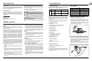
4. Maintenance
4.1 General recommendations
• After the fi rst two or three anchor recoveries, check the
mounting nuts to ensure that the windlass is still fastened
tightly to your deck, as it should now be bedded-in.
• Regularly wash down the exterior of your windlass with fresh
water.
• Examine all electrical connections for possible corrosion,
clean and lightly grease as necessary.
• Anchor rode splice should be checked regularly and remade
if there is any evidence of wear.
• The Gypsy should be examined on a regular basis, because it
is a high wear item. The Gypsy is designed for short scopes
of chain and will last longer if properly used.
5. Dismantling procedures
Isolate the windlass electrically, before carrying out any
maintenance work.
Isolate the windlass electrically, before carrying out any
maintenance work.
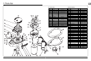
5.1 Gypsy replacement
Remove the Gypsy Drive Cap (31), anti-clockwise using the clutch
operating lever. Withdraw the Drive washer (21), Remove the
Socket Head Cap Screw (40) that retains the Stripper using a
(5mm) Allen Wrench. Pull the Control Arm (30) back to clear the
Gypsy. Remove the Gypsy Assembly (37). To replace the Gypsy,
reverse the above procedure.
5.2 Control arm replacement
This should be carried out with the Gypsy (37) removed as
detailed above. To remove the Control Arm (30). Unscrew the
Control Arm Shoulder Screw (24) using a (4 mm) Allen Wrench
and remove screw. Remove the Control Arm (30) and Torsion
(12) Spring from the base plate. To replace the Control Arm,
reverse the above procedure.
5.3 Main shaft lubrication
Note The geartrain and its bearings have been lubricated for you
with SFG 100 grease and should require no regular attention.
SFG is a white synthetic grease containing PTFE. Use grease
of a similar specifi cation throughout. It is recommended that
the external Drive Shaft components be stripped, cleaned and
re-greased at least annually. To do this, the Gypsy Assembly (37)
should be removed as detailed above. Inspect the Main Shaft (20)
and Gypsy (37) for damage before reassembly.
5.4 Fall safe pawl replacement
This should be carried out with the Gypsy (37) removed as
detailed above. Turn the fall safe lever (34) so it is horizontal.
Remove fall safe shoulder screw (35) using allen wrench. Lift off
fall safe pawl (32). Remove fall safe spring (36). Replace new part
by reversing the above procedure.
5.5 Fall safe lever replacement
Turn fall safe lever (34) so it is horizontal. Remove socket screw
(6) using allen wrench. Remove fall safe lever (34). To refi t use
thread lock on the socket screw (6). Screw down screw (6) fi nger
tight and leave to cure before operating fall safe lever (34).
6. Troubleshooting
6.1 Anchor rode pays out independently
while windlass is not in use
This problem is a result of not securing the anchor rode combined
with the Gypsy Drive Cap (31) being slack. Tighten the Gypsy
Drive Cap using the tool provided and always secure the anchor
rode independently of the windlass whenever it is not being
deployed or recovered.
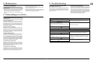
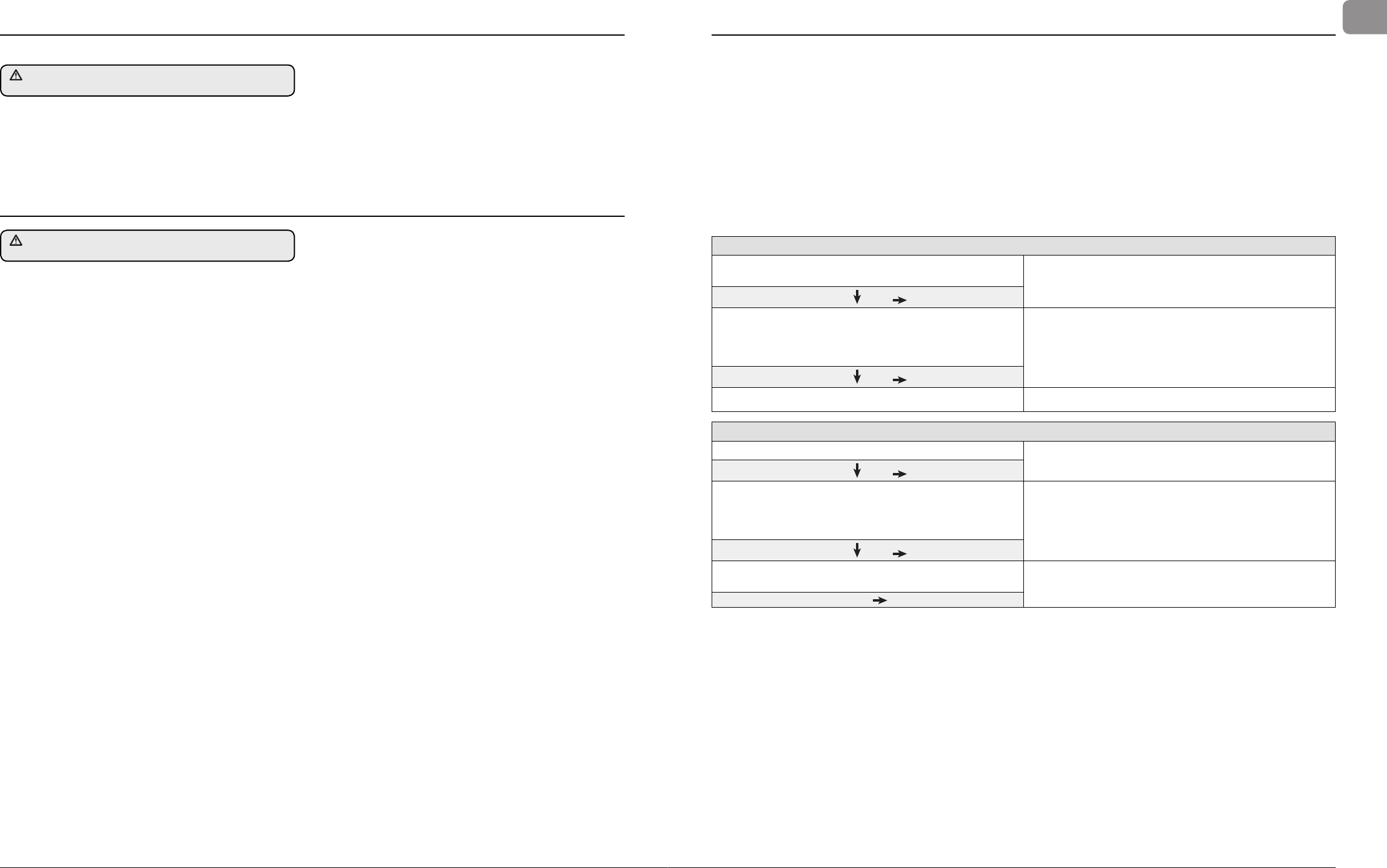
Failure to Operate Troubleshoot Chart: Reversing Toggle Control Switch (Part No. 0052519)
Is there voltage at the input terminal (positive) to the control
switch?
If no voltage is present, the battery isolation switch is OFF, the
breaker is tripped or a fuse has blown. The battery may also
have been dead or disconnected.
YES
NO
Check voltage at the output terminals of the control switch
with the switch on forward then reverse.
Is there voltage at either output terminal for forward then
reverse.?
Control switch is defective.
YES
NO
Replace motor.
Sluggish Operation Troubleshoot Chart
Is windlass overloaded?
Ease the load and ensure the battery is well charged.
YES
NO
Check the voltage across the motor leads with the windlass
on. (Proper voltage is 13.5 V. Constant low voltage will destroy
the motor).
Is the voltage low? (Below 11.0 V on a 12 V system).
There is a severe voltage drop in the circuit.
Check for undersized cables, poor connections or corroded
connections. Also check for resistance across the battery
isolation switch or solenoid. (Feel them to see if they are
heating up).
YES
NO
Is the voltage correct? (Above 11.0 V and anchor is not
fouled).
The motor is defective. Replace the motor.
YES
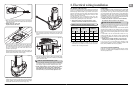
6.2 Electrical troubleshooting
As with most electrical marine equipment the majority of problems
that arise are electrical in nature. Therefore it is essential that
the proper voltage be maintained. The proper voltage on a 12
Volt system is 13.5 Volts. (Constant low voltage will destroy the
motor). Ensure that electrical cable size is large enough to handle
the current draw imposed upon it and to keep the voltage drop
within acceptable limits. In any circumstance voltage drop due
entirely to cable resistance should not exceed 10%.
Follow the charts to troubleshoot the problem.