


8
V700 Windlass
9
V700 Windlass
GB
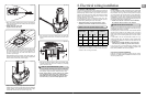
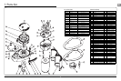
Choice of cable thickness depends on total cable length:
A + B + C + D + E =
Battery to windlass, windlass to battery.
BATTERY
12 VOLT
+
C
D
E
B
A
Rear View on
Toggle Switch
0052519
35 A Breaker/Isolator
68000604 - 12 V
Fuse
3 A
Fig. 2.4-1
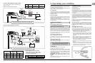
2.4 V700 Wiring diagram (toggle switch)
Model Motor Breaker / Isolator Contactor
V700 12 V 35 A (68000604) N/A
As a prudent act of seamanship, anchor recovery operations
require the undivided attention of skipper and crew to prevent
personal injury or damage to the vessel.
In a typical anchor recovery situation, the windlass will pass
through a number of operational phases.
3.1 Safety fi rst
To avoid personal injuries ensure that limbs, fi ngers and clothing
are kept clear of the anchor rode and windlass during operation.
Always ensure that there are no swimmers or divers nearby when
dropping your anchor.
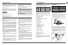
3.2 Use of clutch
To tighten the clutch - using the clutch lever supplied, rotate the
gypsy drive cap (31) clockwise, this will grip the gypsy, effectively
locking it to the windlass geartrain.
To slacken the clutch - turn the gypsy drive cap anti-clockwise,
this will free the gypsy allowing it to turn independently of the
windlass geartrain.
3.3 Letting go under gravity
Insert the clutch lever into the gypsy drive cap (31) and turn
it clockwise to ensure that the clutch is tight. Release any
independent anchor locks. If it is safe to do so, pull back on the
clutch lever until the anchor and rode begin to pay out. Control
the rate of decent of the anchor by pushing the clutch lever
forwards. When suffi cient rode has been paid out, fully tighten
the gypsy drive cap once again.
3.4 Letting go under power
Release any independent anchor locks.
If it is safe to do so, let go under power by operating a ‘Down’
control. Release the control when suffi cient rode has been paid
out.
3.5 Lying to anchor safely
Vessels at anchor will snub on the rode and this can cause slippage or
apply excessive loads to the windlass.
3.6 Hauling in
Untie the bridle or replace the rode in the gypsy.
If it is safe to do so, operate an ‘Up’ control.
The fallsafe pawl (32) does not need to be disengaged during
retrieval as it will act as a ratchet. When the anchor has been
retrieved and is stowed in the bow roller, the fallsafe pawl should
be left engaged in the gypsy to prevent accidental deployment of
the anchor whilst underway.
REMEMBER - The fallsafe pawl DOES need to be
disengaged from the gypsy before the anchor can be let
go again.
Having retrieved the anchor, ensure it is independently secured
to prevent its accidental release.
3.7 Manual recovery
Insert clutch lever supplied into gypsy drive cap (31) and turn clockwise
to haul in the anchor.
3.8 Operating tips
When anchoring, it is best to power the rode out, allowing the
vessel to take up stern way before full scope is let out. This helps
prevent the rode from becoming tangled on top of your anchor
on the seabed.
To aid anchor recovery, we recommend that the vessel’s engine
be used to assist by moving the vessel towards the anchor. We do
not recommend that the vessel be motored over and beyond the
anchor, as this can cause the rode to damage your topsides.
As the anchor approaches the stemhead, the last few feet of rode
should be inched in by judicious use of controls to avoid damage
to the vessel.
Having retrieved the anchor, ensure the fallsafe pawl is engaged
in the gypsy to lock it and prevent accidental deployment of the
anchor whilst underway.
When mooring stern to, at a suitable distance from the jetty,
deploy the anchor to prevent the bow from swinging. Gently pay
out the rode under the infl uence of the stern way of the vessel
as it approaches the jetty. Make fast your vessel with warps from
the stern.
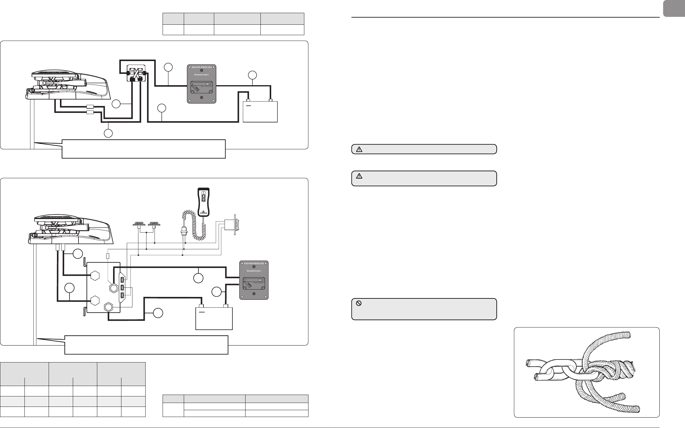
3.9 Joining rope to chain
When splicing rope to chain, select a length of chain that will
avoid having the splice positioned in the gypsy when the anchor
comes over the stemhead. Furthermore, ensure that the splice
is no tighter than the rope. A hard splice is not desired.
• With whipping twine or similar, seize your rope 200 mm (8”)
from the rope’s end and unlay the strands.
• Pass one strand through the chain link from one side and the
other two strands from the opposite side. Remove seizing
and complete a back splice in the normal manner for four
full tucks.
• With a hot knife pare down the three strands by one half of
their diameter and continue with two further tucks.
• With a hot knife, carefully melt the ends back into the line.
Because of wide variations in rope type and construction
some experimentation may be required.
• Whip the line with permanent whipping at the beginning of
the taper.
• The above method of joining is designed to minimize chafe
between the rope and chain but as a matter of prudent
seamanship the splice should be checked regularly and
remade if there is any evidence of wear.
Fig. 3.9-1
3. Operating your windlass
Always remove the handle after use.
For maximum safety and to prevent damage, the fallsafe pawl MUST NOT
be left to take the entire force from the anchor rode while at anchor. The
rode should be made fast directly to a bollard, sampson post or cleat.
Always check the fallsafe pawl (32) is disengaged from the gypsy
and held clear of it by the fallsafe lever (34).
Boat Length
Cable Length
Up To
Cable Size
(m) (ft) (m) (ft) (AWG) (mm
2
)
7.5 25 0 - 10 0 - 33 8 10
9 30 11 - 18 34 - 60 6 16
10.5 35 19 - 24 61 - 80 4 25
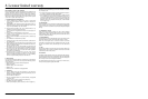
Small red and black sleeved wires are sensor wires to chain counter if fi tted.
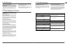
• NOTE: Wireless remote also available.
Model Item Description
Wireless
Remotes
68000844 3 Button Windlass only
68000845 5 Button Windlass & Thruster
• NOTE: Wireless remote can only be used
if a contactor is fi tted. See wireless remote
instructions for wiring details.
35 A Breaker/Isolator
BATTERY
Fuse
3 A
Contactor
0052531 - 12 V
68000604 - 35 A, 12 V
E
A
B
D
C
+
+
BATTERY
12 VOLT
Guarded Rocker
Switch
68000593
Shared
Down
Up
DOWN UP
Deck Fott Switch Set
68000598 Black
68000597 White
Hand Held Control
68000599
R
Fig. 2.5-1
2.5 V700 Wiring diagram (contactor)
Small red and black sleeved wires are sensor wires to chain counter if fi tted.