


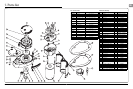


6
V700 Windlass
7
V700 Windlass
GB
DO NOT use a permanent adhesive/sealant, e.g., 5200
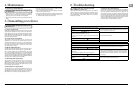
• Using a 10 mm (
3
/
8
”) diameter drill, make the three holes
for the mounting studs. With a 65 mm (2
1
/
2
”) diameter hole
saw, make the hole for the rode to pass throughwith a 115
mm (4
1
/
2
”) diameter hole saw, make a hole for the motor
gearbox to pass through.
When all the holes have been made, remove the template. To
help avoid water absorption by the deck, apply an appropriate
marine sealant to the freshly cut hole edges.
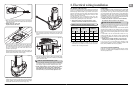
Fig. 1.6-4
• Place the mounting template on the deck or mounting pad
in the desired position for the windlass and hold it in place
using adhesive tape.
• NOTE: Check the scale of the
template matches the winch.
Fig. 1.6-5
• Fully screw the three mounting studs into the base of the
windlass. This can be done, quite simply, using the multi-tool
wrench supplied. Screw the studs into the base fi nger tight,
with the fl ats towards the base as shown (Fig 1.6-5).
• Next, using the wrench on the fl ats, tighten the studs until
they bottom out in their holes. Do this to each of the studs
in turn.
Fig. 1.6-6
As a rule of thumb, if the fl ats on the studs are visible below
deck, the deck and/or any packing is likely to be too thin to
offer adequate support when the windlass is under load.
• NOTE: If using silicone or other rubbery type sealant,
it is advisable to allow curing of the sealant before
fi nal tightening of the mounting nuts. Trim the studs
back to 6 mm (
1
/
4
”) below the fully tightened nuts.
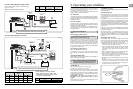
2. Electrical wiring installation
2.1 Electric cable selection
To achieve the best performance and to safeguard your electrical
system it is essential that any electrical windlass be fi tted with
suffi ciently large diameter cable to cope with the current draw
imposed upon it and to keep the voltage drop within acceptable
limits. In any circumstance voltage drop due entirely to cable
resistance should not exceed 10%.
The following table gives recommended cable sizes. The
recommendations are based on total length of cable required,
from the battery, following the route of the cables.
• Total length of cable run is from the battery to the
windlass, and from the windlass back to the battery.
• In Multi Station installations 14 AWG wire (1.5 mm² cross
sectional area, 21/0.30 PVC covered) is used to connect the
switches to the reversing control box.
2.2 Wiring
Plan the installation to suit the controls and give the operator a full
view of the windlass. The wiring system should be of the two cable
fully insulated return type, which avoids possible electrolytic
corrosion problems. We recommend the use of type III stranded,
tinned copper wire with copper crimp terminals. Most modern
installations are negative return (negative ground) but polarity
should be checked. If necessary add a grounding strap between
the mounting studs and an earthing point.
• NOTE: If a Contactor is used in a V700 installation,
the Contactor must be sited in a dry location.
If a contactor is installed in an anchor locker it is exposed to harsh
conditions it is not designed to withstand. Furthermore this type
of installation will void your warranty.
Overload protection, in the form of the circuit breaker/isolator
supplied, must be built into the windlass wiring circuit. This
protects the wiring and prevents undue damage to the windlass
motor, in the event of its being stalled by an excessive load in
service.
It is advisable to site the circuit breaker/isolator in a dry,
readily accessible place. The Breaker/ Isolator supplied must
be manually reset should an overload occur that causes it to trip
to the off position.
• NOTE: Crimp terminals should be used on all wire
ends wherever possible for good electrical contacts.
If you are not sure you understand these guidelines, seek
professional help. Ensure that the installation complies with
USCG, ABYC, NMMA or other local regulations.
2.3 Control switch installation
Follow the mounting instructions supplied with the switch.
Remember, in a Multi Station installation all switches must be
wired in a parallel circuit.
DO NOT confuse cable Length with the length of the vessel!
DO NOT install the contactor in the anchor locker.
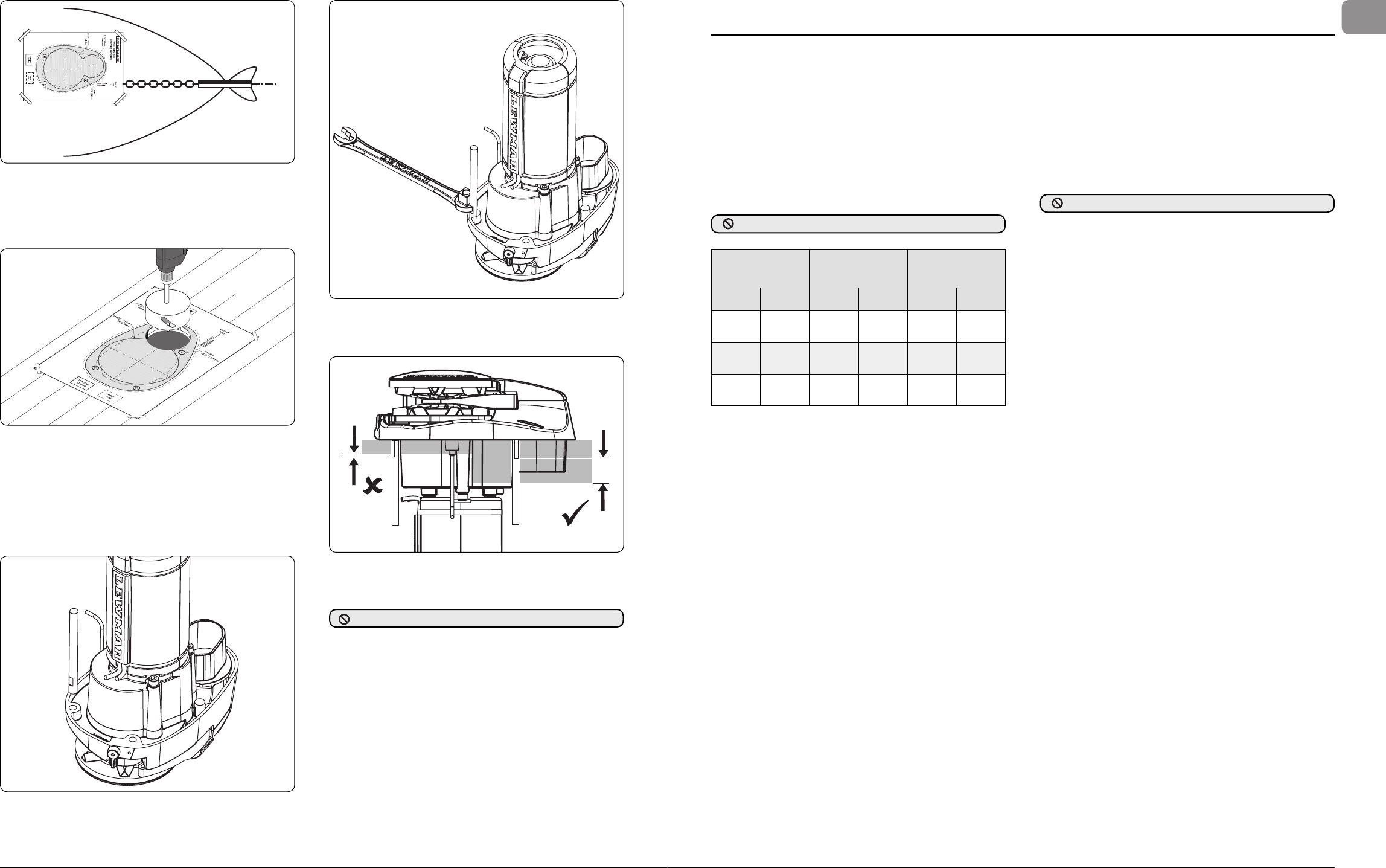
Fig. 1.6-3
• Place the base mat in position on the deck, optionally, apply
a suitable sealant to the base of the windlass, any mounting
pad or around the studs.
Fig. 1.6-7
Boat Length
Cable Length
Up To
Cable Size
(m) (ft) (m) (ft) (AWG) (mm
2
)
7.5 25 0 - 10 0 - 33 8 10
9 30 11 - 18 34 - 60 6 16
10.5 35 19 - 24 61 - 80 4 25