


LANIER – 1/3
rd
Scale Laser 200 ARF -INSTRU CTIONS
© 2002 Lanier R/CPage-8
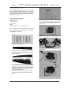
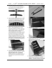
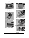
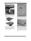
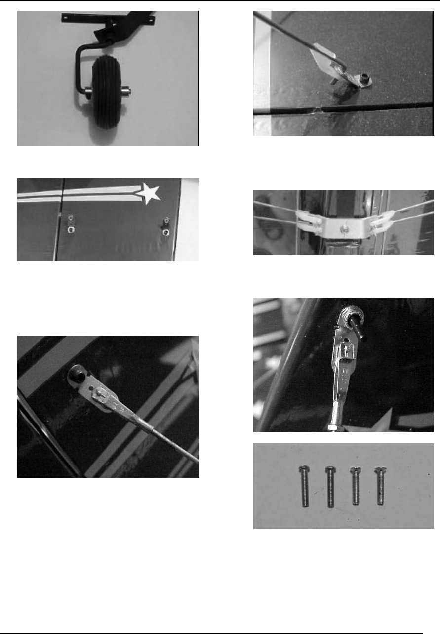
46. Install the tail w heel on the axle, then secure
with the sm all w heel collar and set screw . Use
som e thread lock on the screw .
47. Locate the hard points in the tail surfaces for the
tail brace wires. Pierce the covering with a sharp
blade. Put a slight bend in (12) of the tail wire
brackets, then install them in the horizontal and
vertical stabilizers as show n, with a bracket on
both sides of the surfaces. Use a 4-40 screw and
lock nut on each bracket.
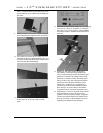
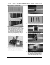
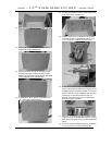
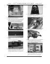
48. Install a 2-56 clevis on the ends of the (8) 2-56
threaded rods, then install (4) rods in the middle
hole of the vertical braces.
49. M ark the length of the rods about ¼” past the
largest hole in the horizontal braces, then trim.
B end at 90 degrees, then insert in the hole.
Secure with an L connector. Adjust at the clevis
end, but don’t warp the horizontal surface.
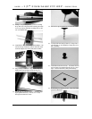
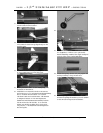
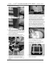
50. Install the tail brace bracket using the rear #6
screw . A ssem ble the other (4) tail brace wires
the sam e as the top, then secure with the L
connectors.
51. M ake sure each clevis gets a keeper installed.
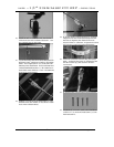
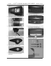
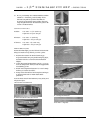
52. Locate the (4) 4 x 20mm screw s for installation
of the cow l. (2) are round head screw s, (2) are
flat head screw s.