


LANIER – 1/3
rd
Scale Laser 200 ARF -INSTRU CTIONS
© 2002 Lanier R/CPage-11
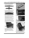
firew all, behind the blind nuts.
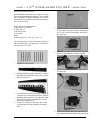
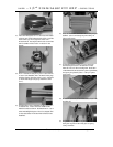
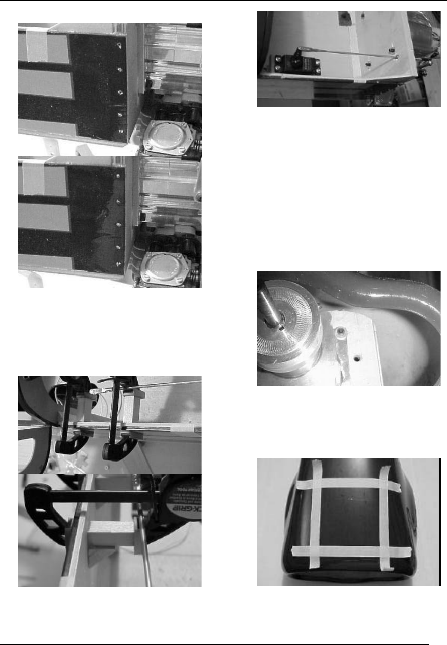
69. D rill (5) 3/32” holes on each side of the firew all,
through the fu se sides about 1” deep. Press a
w ood toothpick into the hole, then cut off flush
with som e wire snips. A pply several drops of
thin CA on each toothpick.
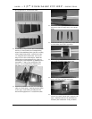
70. M ark on the firew all the location where the
throttle contro l rod should pass through. Drill
the marked hole with a 1/8”aircraft drill bit.
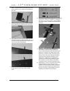
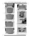
71. U sing your servo as a guide, glue the two
hardw ood servo blocks to the fuse side using 30
minute epoxy. Cut a sm all piece of balsa
triangle stock to fillet the servo rails and fasten
with CA.
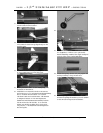
72. M ake sure your carburetor and throttle servo are
at low position. Reverse your servo if necessary.
Thread the 2-56 clevis on the 12” rod, then snap
the clevis on the servo arm. Install an EZ
connector in the hole on your carburetor
approximately the sam e length of the servo arm.
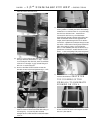
Trim the throttle control rod to approximate
length, then insert through the hole in the EZ
connector. Tighten the connector enough to test
the throw of the servo and adjust as needed to
allow for maximum throw , but not bind the
servo. When satisfied, trim the control rod to ¼”
past the EZ connector. In stall the servo horn
screw . When everything is fit, th en fuel proof
the firew all with polyurethane or thinned epoxy.
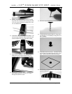
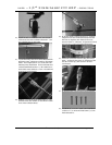
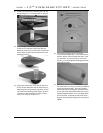
73. Test fit the cow l over the engine to see what
needs to be relieved.
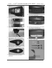
SHAVE TH E
TOP CORNERS OF TH E
FIREW ALL TO ELIM INATE
RUBBING ON COW L.
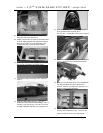
74. U se masking tape to mark the areas that need to
be rem oved for the head of the engine to clear
the cow l, then test fit.