Delta 1200 Technical Manual 07610-003-62-15 G
Issued: 10-27-2008 Revised:05-21-2012
SECTION 5: SERVICE PROCEDURES
REPLACING THE CHEMICAL FEEDER PUMP MOTOR
17
Jackson glasswasher machines come equipped with
chemical feeder pumps to ensure proper ware washing
results. Occasionally, the motors operating these pumps may
need replacing to maintain optimum performance.
Jackson offers all of the repair parts necessary for
performing this task.
The instructions provided here are for maintenance
personnel only. Unauthorized persons should not attempt any
of the steps contained in these instructions.
Warning: many of the instructions and steps with-
in this document require the use of tools. Only authorized
personnel should ever perform any maintenance proce-
dure on the dishmachine!
PREPARATION
1. Power must be secured to the unit at the service
breaker. Tag or lock out the service breaker to prevent acci-
dental or unauthorized energizing of the machine.
2. Ensure that incoming water to the machine is
secured either by use of a shut-off valve or disconnecting the
incoming water line.
3. The unit must be drained completely with the drain
stopper removed.
TOOLS REQUIRED
The following tools will be needed to perform this
maintenance evolution:
1. Phillipshead Screwdriver
2. Needlenose Pliers
3. Wire Cutters
4. Wire Strippers
5. Crimping Tool
TIME REQUIRED
It is estimated that it will take (1) person thirty minutes
per motor to perform this task, not including all of the items
indicated in the section entitled “PREPARATION”.
IMPORTANT NOTES
1. Read these instructions thoroughly before attempt-
ing this maintenance task. Become familiar with the parts and
what actions need to be taken. This will save time in the long
run!
2. These instructions show steps on only (1) of the
three motors. However, the steps are the same for each one.
STEPS
1. Remove the front door.
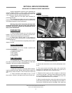
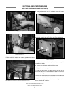
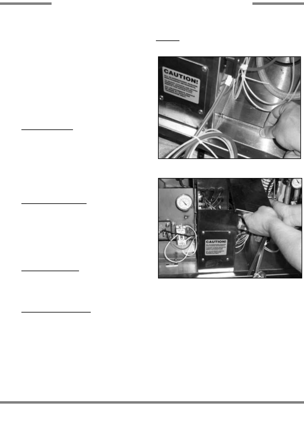
2. Remove the electrical box cover with the phillipshead screw-
driver.
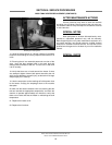
3. The cover must be laid down close to the control box
because of the attached wires. Be careful not to yank out or
damage any of the wires as you move the cover.
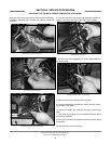
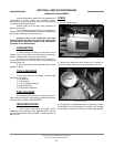
4. Determine which motor you wish to replace, or which one
you wish to start with. Trace the wires leading from the motor
to its corresponding prime switch. Trace the other wire from
the motor to determine where it is connected.
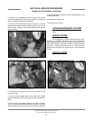
5. With the needlenose pliers, remove the motor wire from the
prime switch, being careful not to damage the prime switch in
the process. (If the prime switch is damaged, it will need to be
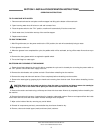
Removing the screws for the electrical box cover.
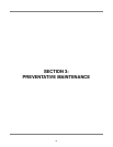
Removing the electrical box cover.


