


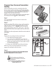

20 GTO 4000XLS Instruction Manual © 01.10.12
GRNCOMCOM
CYCLE
CLOSE
SAFETY
SHADOW
LOOP
CLOSE
EDGE
OPEN
EDGE
EXIT
OPEN
BLK
RECEIVER
RED
ALM
ORGLUE BRN RED
STER INPUTS
BLK
STER CABLE
CONTROL INPUTS
1
2 3
4
5
6
7
SOLAR
or
18 VAC
WGRN
LOCK
PWR
AUX
RLY
TRANSF
LOCK
PWR
AUX
RLY
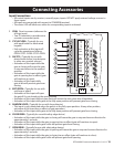
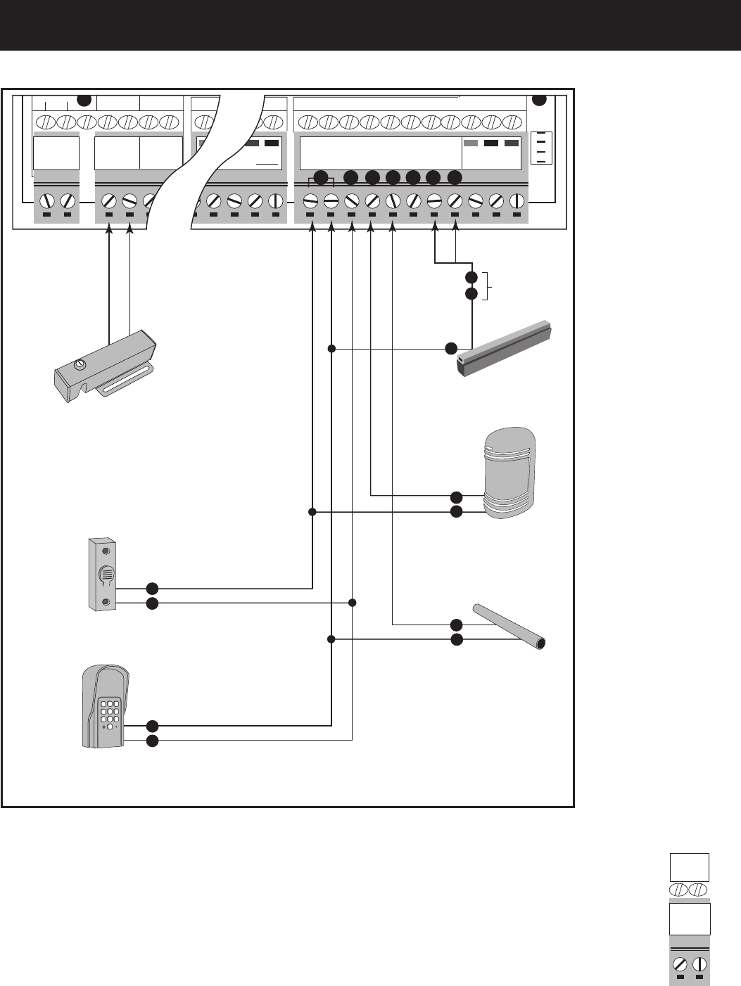
Photo Beams
Loop Detector
Push Button Control
Automatic Gate Lock
According to
Application
According to
Application
Vehicle Sensor
Refer to Vehicle Sensor
manual for additional
connections.
Edge Sensor
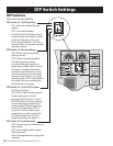
ON
1 2 3 4 5 6 7 8 9 10
DIP
NO
COM
NC
V +
V –
LOOP
LOOP
LOOP
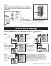
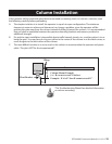
NOTE: Connections are for typical applications.
There may be additional connection options for
applications that are not illustrated here.
2
1
1
1
3
1
1
Digital Keypad
3
4
5
4
1
2
1
2
ABC
3
DEF
4
GHI
5
JKL
6
MNO
7
PRS
8
TUV
9
WXY
0
7
6
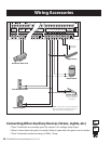
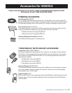
Connecting Other Auxiliary Devices (Sirens, Lights, etc.)
• These2terminalsarenormallyopen“dry-contact”(novoltage)relayouput.
•Relayisclosedwhenthegateisinmotion;Relayisopenwhenthegateisnotinmotion.
•These2terminalsmaximumratingis24Vdc,1Amp.
Wiring Accessories
AUX
RLY
AUX
RLY