


14 GTO 4000XLS Instruction Manual © 01.10.12
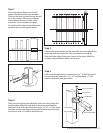
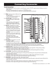
Step 5
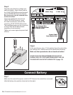
Strip the ends of the low voltage wire
and twist tightly. Attach these ends to
the 18 VAC OR SOLAR terminals located
on the POWER INPUTS terminal block.
Be certain not to let the exposed wires
touch each other!
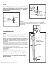
Insert one transformer wire into an
18 VAC OR SOLAR terminal. Insert
the other transformer wire into the
remaining 18 VAC OR SOLAR terminal.
The transformer wires can be connected
to the 18 VAC OR SOLAR terminals
regardless of color/polarity.
Tighten set screws against exposed end
of wires.
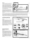
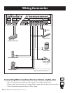
Step 6
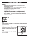
At the transformer, strip
1
/2” of insulation from the ends of the
low voltage wire. Attach wires to the transformer terminals.
Make sure the exposed wires do not touch each other!
DO NOT PLUG THE TRANSFORMER INTO AN OUTLET
DURING THIS STEP! THE TRANSFORMER MUST ONLY BE
PLUGGED INTO AN OUTLET DURING STEP 3 (page 15)!
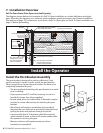
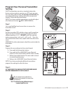
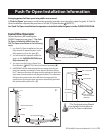
Step 1
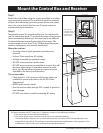
Make sure the control box power switch is OFF. Remove the control box cover and
slide the battery into position (terminals to the right).
Connect Battery
~~
ORGBLUEWHTGRN BRN RED
MASTER OPERATOR
BLK
18 VAC
OR
SOLAR
ORGBLUEWHTGRN BRN RED BLK
LOCK
PWR
AUX
RLY
LOCK
PWR
AUX
RLY
POWER
INPUT
CONTROL OUTPUTS
MASTER OPERATOR2ND OPERATOR
2ND OPERATOR
Power Cable
from Master Arm
RED
BLACK
Low Voltage Wire
from AC Transformer
or Solar Panel
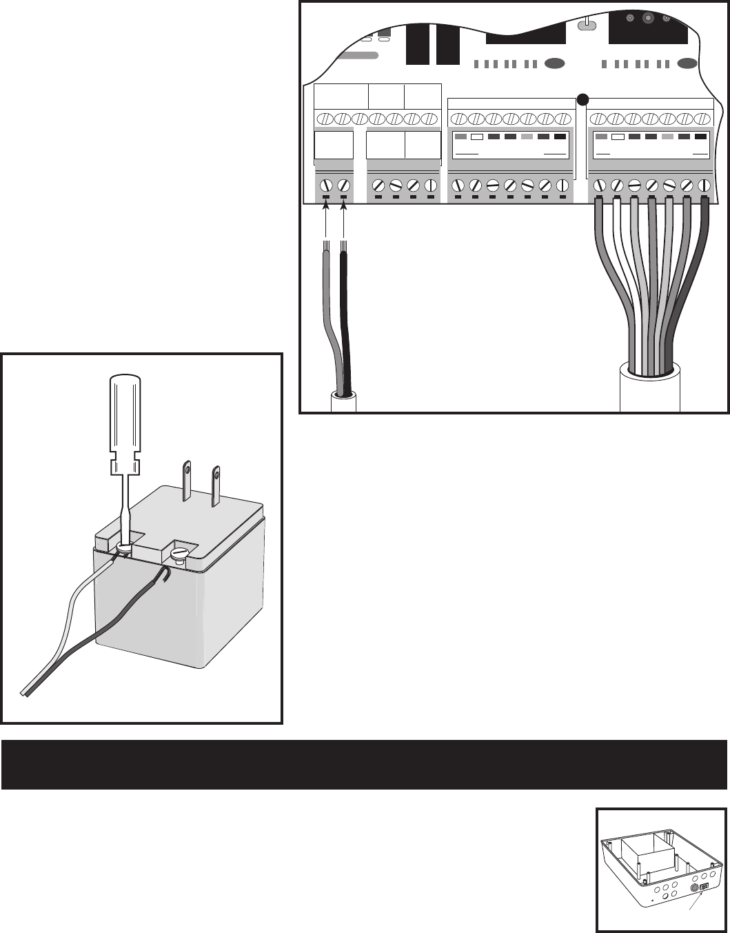
ON/OFF Switch
ON/OFF