


8
Step 1. Turn control box power switch OFF and unplug the transformer or disconnect the solar panel. Remove
control box cover and disconnect battery lead wires from the battery terminals before wiring the lock
board to the opener control board.
Step 2. Connect the WHITE wire (included) to Terminal #1 on the lock board. Connect the RED battery lead
wire (included) to Terminal #5 on the lock board.
Step 3. Attach the RED control board battery lead wire to one spade tongue on a double spade tongue connector
(included). Attach the BLACK control board battery lead wire to one spade tongue on the other double
spade tongue connector (included).
Step 4. Pull RED and BLACK wires from gate lock through the strain relief and into the control box. Attach
BLACK wire to Terminal #3 on lock board. Attach RED wire to Terminal #4 on lock board (see Lock
Board Wiring Chart below).
Step 5. Attach RED lock board battery lead wire to the double spade tongue terminal with the RED control
board lead wire. Attach the BLACK lock board battery lead wire to the double spade tongue connector
with the BLACK control board Lead Wire.
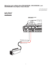
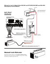
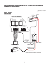
Step 6. Connect the WHITE wire from the lock board directly to the MASTER OPERATOR terminal block
along with the power cable wire from the opener arm. Connect the WHITE wire to the RED terminal
for a Pull-to-Open installation or connect WHITE wire to the BLACK terminal for a Push-to-Open
installation (see illustration on page 9).
Step 7. Reconnect opener to gate bracket. Connect the BLACK Battery lead wire (included) to Terminal #2 on
the lock board. (See Lock Board Wiring Chart below). Connect RED wires (with double spade tongue
terminal) to POSITIVE (+) battery terminal and the BLACK wires (with double spade tongue terminal)
to the NEGATIVE (–) battery terminal. Plug the transformer in or rewire the solar and turn the control
box power switch ON. Test opener and lock to make sure it functions properly and make adjustments if
necessary.
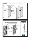
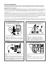
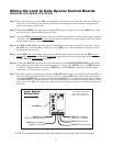
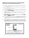
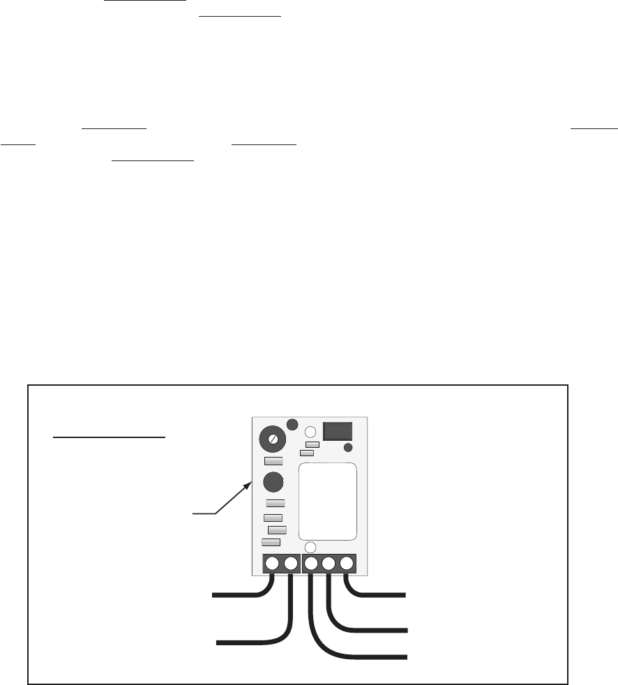
Wiring the Lock to Gate Opener Control Boards
MM500/502, PRO-SW3000, PRO-SW4000
RED Wire To Battery
Positive (+) Terminal
RED Wire From Lock
BLACK Wire From Lock
WHITE Wire to
RED on OperatorTerminal
Lock Board
BLACK Wire To Battery
Negative (–) Terminal
1
2
345
Time Adj
* Place a dab of petroleum
jelly on the terminal con-
tacts to prevent corrosion.
Lock Board
Wiring Chart
NOTE: It is recommended that the time adjustment knob is turned all the way to the right.