


4
SET
LIMIT
LEARN
TRANSMITTER
1
ON
2 3 4 5 6 7
MODES
ON
OFF
1 2 3 4 5 6 7
1
ON
2 3 4
DUAL
MODES
ON
OFF
1 2 3 4
DIP switches
1 2 3 4
ON
OBSTRUCT
SENS.
PULL/PUSH
SEQ1
SNGL/DUAL
SEQ2
LEARN
DIP switches
MIN MAX
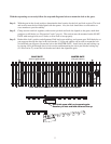
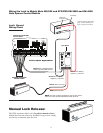
Turn power switch OFF on the bottom of the control box. Disconnect gate openers by removing hairpin clip and
clevis pin from the gate bracket end of the openers. Disconnecting the openers will allow the gates to swing freely
during installation of the gate lock.
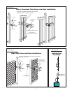
Dual Gate Installation
IMPORTANT: To use the gate lock on a dual gate system, the gate sequencing must be set so the MASTER GATE
opens first and closes last, and the gate lock has to be mounted on the MASTER GATE and the lock receiver is
mounted on the SLAVE GATE. The slave gate requires a positive stop. If your gates are not sequenced in a manner
that works like this, you'll have to change the sequencing DIP switches on your gate opener control board. Follow
the instructions in your gate opener installation manual for programming dual gate sequencing.
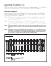
The diagrams below will show how most dual GTO/PRO
®
and Mighty Mule
®
gate sequencing is programmed. If
your gate opener control board is different form these shown, please contact GTO Technical Service at 1-800-543-
1236 for additional information.
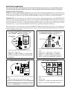
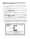
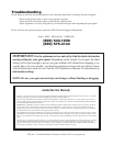
First Operator opens first, Second Operator closes first
SEQ1 = OFF SEQ2 = ON
If SEQ1 is set to OFF, and SEQ2 is set to ON, the FIRST
OPERATOR will open first, and the SECOND OPERATOR
will close first.
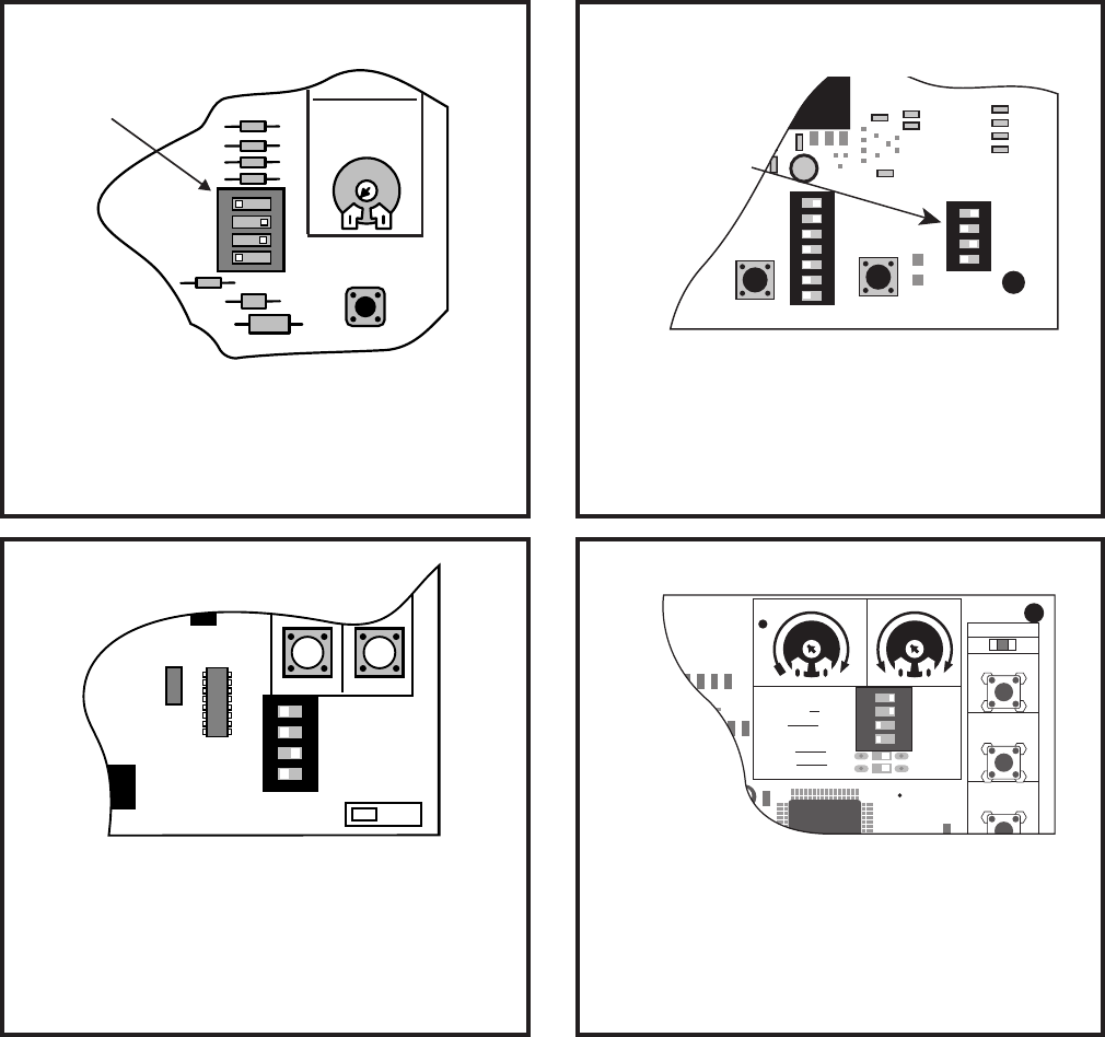
Master opens 2 secs before slave, Slave closes 8 secs before
master.
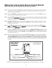
Switch 1 = ON Switch 2 = OFF Switch 3= ON
If Switch 1 is set to ON, Switch 2 is set to OFF and
Switch 3 is set to ON, the MASTER OPERATOR will
open first, and the SLAVE OPERATOR will close first.
Master opens 2 secs before slave, Slave closes 8 secs before
master.
Switch 4= OFF
If Switch 4 is set to OFF, the MASTER OPERATOR will
open first, and the SLAVE OPERATOR will close first.
Master opens 2 secs before slave, Slave closes 8 secs before
master.
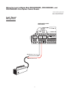
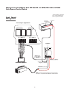
Switch 2 = OFF Switch 3 = ON Switch 4 = OFF
If Switch 2 is set to off and Switch 3 is set to on the MASTER
will open first and the SLAVE operator will close first. Switch 4
must be set to LOCK MODE to avoid damaging circuit board
For Mighty Mule
®
FM502, GTO/PRO
®
3000
and GTO/PRO
®
4000 Dual Gate Openers
NOTE: In a DUAL GATE INSTALLATION the gate opener on the same side of the driveway as the control box is
known as the MASTER GATE OPENER and that gate is refered to as the MASTER GATE. Conversly the gate opener
on the other gate is refered to as the SLAVE GATE OPENER and the gate is refered to as the SLAVE GATE.
For Mighty Mule
®
FM702, GTO/PRO
®
1000
and GTO/PRO
®
2000 Dual Gate Openers
Mighty Mule
®
350 Control Board Gen - 3 (Blue) Control Boards
1
ON
2 3 4
CHARGING
RF
PULL-PUSH
MODE1
MODE2
LOCK/BEACON
CLOSE TIME
SET
LIMIT
LEARN
REMOTE
1 2 3 4
ON DIP
STATUS
LEARN RMT
LEARN
MAST LIMIT
LEARN
SLV LIMIT
S3
S4
S2
OFF
SOFT START OFF
WARNING OFF
OPEN PULL
SLV OPEN DLY.
MODE1 OFF
MODE2 OFF
ON
ON
PUSH
SIMULT.
ON
ON
120 MIN MAX
AUTO CLOSE TIME STALL FORCE