


5
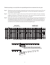
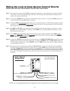
Step 1: With the gate in the closed position, determine the best location for the lock and lock receiver. The lock
and receiver must be level and aligned with the opener. Also, the lock should have a solid surface or
cross member to provide stability.
Step 2: Clamp receiver and lock together (with receiver pin hole and lock slot aligned) to the gates, mark their
positions to drill holes (see Illustration E and F, page 6). The receiver must be mounted on the SLAVE
GATE with carriage bolts, not U-bolts, to allow lock to seat properly.
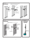
Step 3: Recheck the lock's position and alignment. Hold latch open with key and operate gate. Drill the holes on
gate supports through the slots in the lock bracket. U-bolts and saddles can be used to mount the lock
on chain link gate supports. Secure the lock to the MASTER GATE. Install clevis pin and locking cap
by placing clevis pin through slots in lock receiver and hammering the clevis pin into the locking cap
(see Illustration G), secure the lock bracket and check the alignment again.
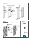
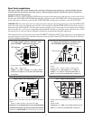
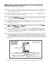
With the sequencing set correctly follow the steps and diagrams below to mount the lock to the gates.
Lock and receiver must be level and aligned with opener.
Hold latch open with key to operate gate.
Receiver pin hole and lock slot must line up.
MASTER GATE
SLAVE GATE
(second gate opener) (first gate opener)
500
500
500