


1
The installation has two parts:
(1) Mounting The Lock and Lock Receiver
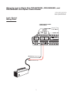
(2) Connecting the Control Boards
Once you have the necessary mounting hardware, you can begin the installation.
Before You Start...
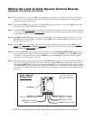
For the GTO Automatic Gate Lock to work properly, the gate must close firmly against a positive stop and
engage the lock catch against the lock receiver. Achieving optimal closure may require slight adjustments to
the gate opener settings.
Installing the lock with the Gate Opener may require resetting closed limits and changes to the stall force.
See Setting the Gate Closed Position in your Gate Opener Installation Manual for information on these
adjustments.
Set the limits so that the arm holds the gate snug against the stop in the closed position. IMPORTANT: You
may need to spray the locking mechanism with silicone spray initially to help the latch move freely.
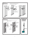
If you are installing the lock on a Push-to-Open gate (gate opens out), the lock must be installed on the outside
of the gate. Depending upon the installation, the gate post may need to be "pocketed" to accommodate the
lock receiver or you may want to purchase the column mount receiver. Contact the GTO Technical Service
Department at (850) 575-4144 for assistance if needed.
NOTE: Positive stops are required for dual gate applications.
AUTOMATIC
GATE LOCK
®
D
E
F
G
H
I
J
K
L
M
C
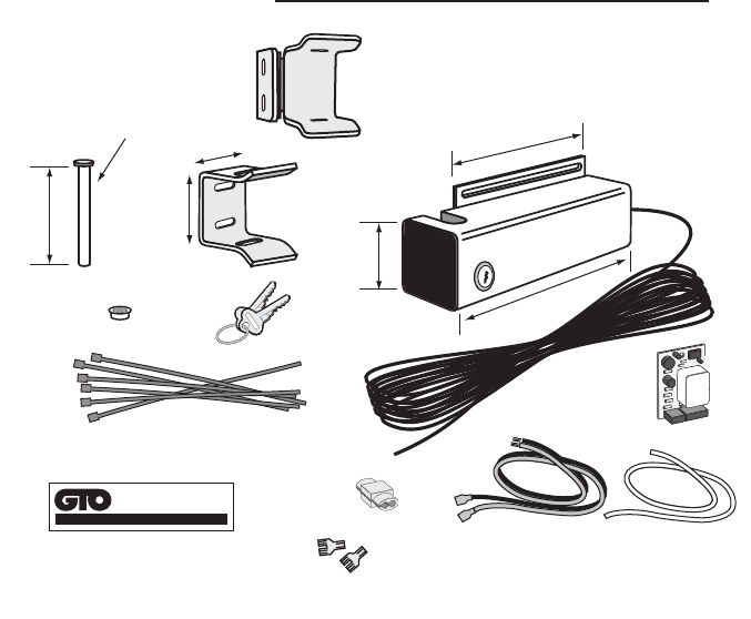
3½”
¼” Diameter
Optional
Column Mount Receiver
433IH (not included)
B
2”
2¾”
A
2”
5½”
8½”
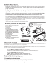
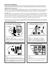
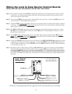
Be sure you have all the parts:
A - Lock with 20' of low voltage wire
B - Lock Receiver
C - Clevis Pin
D - Locking Cap
E - Lock Board Battery Lead Wires
F - White Wire
(motor lead to lock board)
G - Lock Control Board (Lock PCB)
H - 2 Double Spade Tongue terminals
I - 6 nylon cable ties
J - Wire Connector
K - Lock Keys (for manual release)
L - Lock Decal
M - Optional Column Mount Receiver
433IH (not included)
What else do you need?
Mounting hardware is not included. Read these instructions completely and review the installation examples to
determine the mounting hardware required for your application.
NOTE: The GTO Lock is designed to use mounting hardware up to
5
/16" in diameter. For a more secure installation,
use lock washers and lock nuts on all mounting hardware.
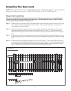
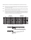
For most IRON or ALUMINUM TUBE gates you will need:
Carriage bolts, washers, and nuts for the lock and receiver. (see Illustration B, page 3)
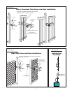
For most CHAIN LINK gates you will need:
U-Bolts, saddles or carriage bolts, washers and nuts for the lock.
Bolts, washers, and nuts for the receiver. (see Illustration C, page 3)